Self-expanding blind fastener with mechanical lock

a self-expanding, blind fastener technology, applied in the direction of fastening means, screws, dowels, etc., can solve problems such as loosening of fasteners, and achieve the effect of preventing loosening rotation

Inactive Publication Date: 2000-03-14
METALDYNE CORP
View PDF28 Cites 47 Cited by
  • Summary
  • Abstract
  • Description
  • Claims
  • Application Information

AI Technical Summary

Benefits of technology

The present invention overcomes the disadvantages of the prior known blind fasteners by providing a fastener which can be installed with robotic equipment, uniformly expands within the aperture, and includes a mechanical lock to resist loosening of the fastener.

Problems solved by technology

However, the vibrations and sonic fatigue such vehicles are subject to cause loosening of the fastener.

Method used


Image

  • Self-expanding blind fastener with mechanical lock
  • Self-expanding blind fastener with mechanical lock
  • Self-expanding blind fastener with mechanical lock

Examples


Embodiment Construction

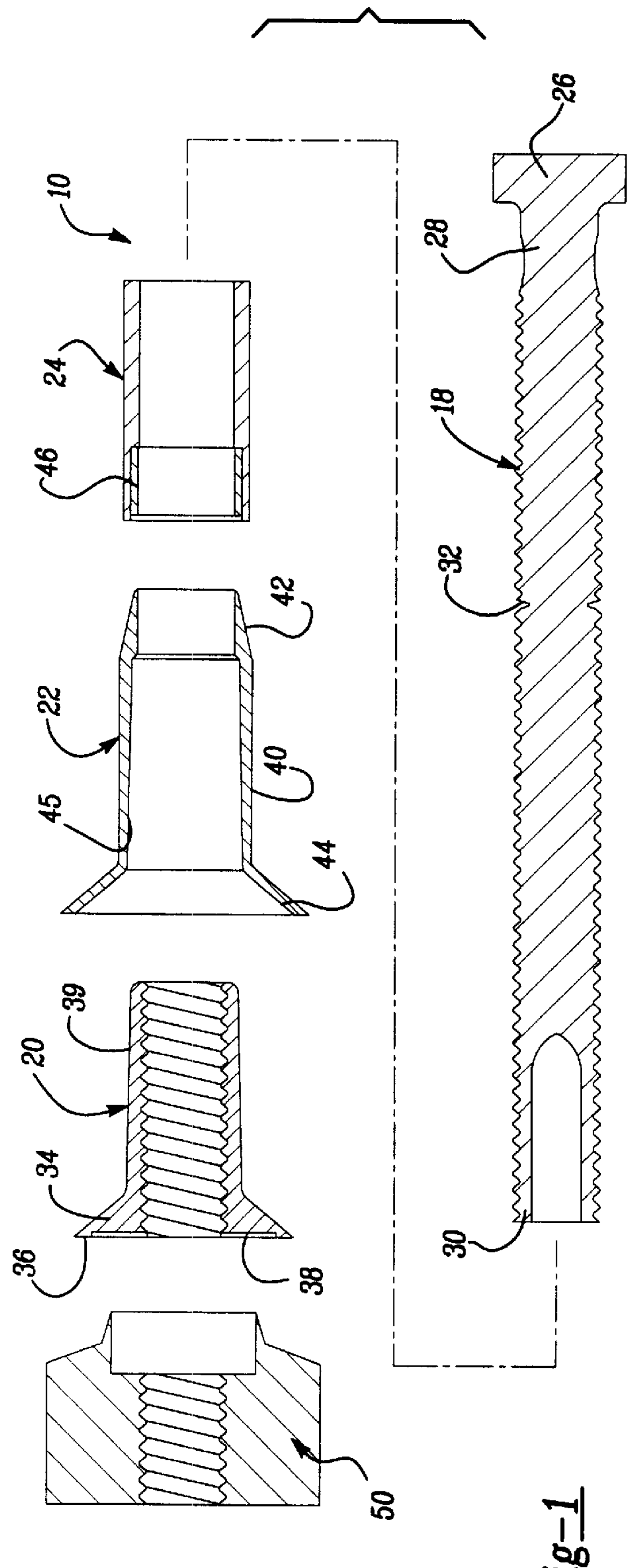
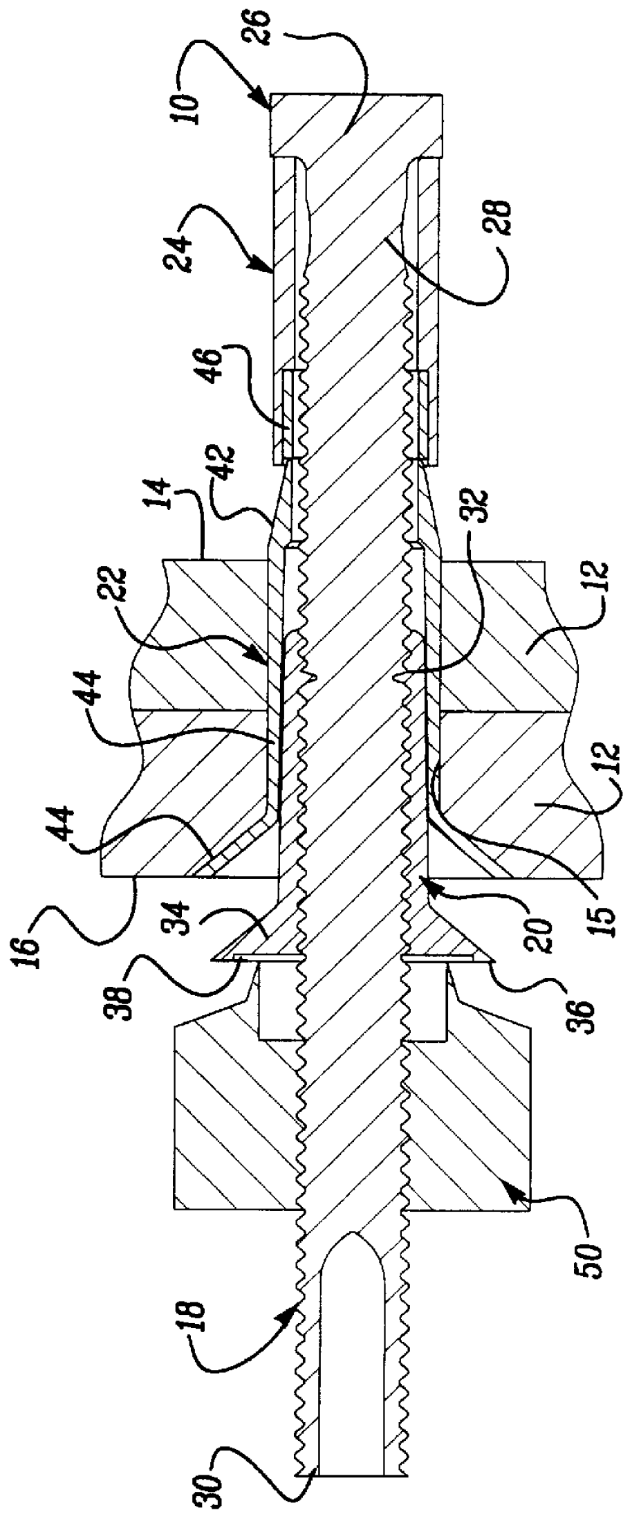
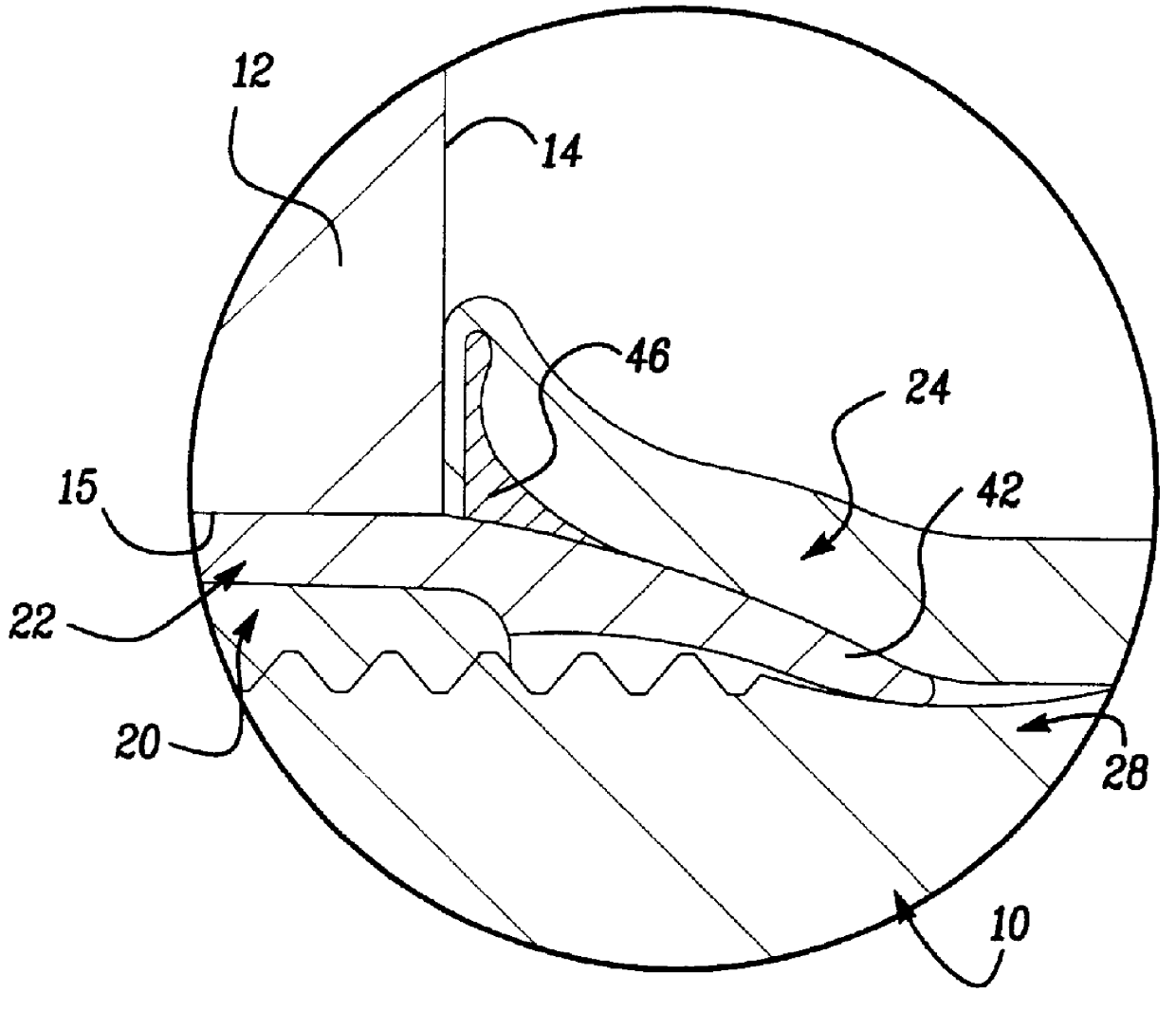
Referring first to FIGS. 1 and 2, there is shown a self-expanding blind fastener 10 for securing materials such as overlapping sheet metal 12. The fastener 10 is designed to create a clamping force thereby holding the sheet material together. The fastener 10 is particularly useful in the assembly of aircraft and space vehicles where access to an interior surface 14 of the sheets 12 is not possible. The outer end of the fastener 10 can be broken away following installation leaving a smooth aerodynamic exterior surface 16. The fastener 10 of the present invention includes a locking feature to prevent the fastener from loosening and losing its clamping force even when the fastener is subjected to high levels of stress and vibration.

The fastener 10 generally includes an externally threaded stem 18, an internally threaded nut body 20, a lock sleeve 22 and an expansion member 24. The threaded stem 18 has an enlarged head 26, a reduced diameter shank or neck portion 28 and a tail 30. The s...


PUM


Abstract

A blind fastener for clamping sheet components and including a mechanical lock to prevent loosening of the fastener. The fastener is self-expanding following insertion and engagement of the threaded stem. The fastener includes an internally threaded nut body, an externally threaded stem threadably received within the nut body, and a lock sleeve matingly receiving the nut body. Carried on the stem is an expandable sleeve which expands to engage the underside of the material. Rotation of the stem following insertion of the assembly into the aperture will draw the stem head and expandable sleeve against the backside for the material causing the sleeve to expand outwardly. In addition, the locking sleeve is pushed beneath the expansion sleeve wedging between the threaded stem and expansion sleeve. This mechanical lock is resistant to vibration locking the fastener against loosening.

Description

I. Field of the InventionThis invention relates to blind fasteners for securing sheet material and, in particular, to a blind fastener with a self-expanding sleeve having a mechanical lock to prevent loosening of the fastener.II. Description of the Prior ArtBlind fasteners have become particularly useful in securing sheet materials where it is impossible to access the underside of the material. Typically such fasteners are inserted into an aperture through the material and include a threaded stem for engaging the fastener. Rotation of the stem draws an expansion member into engagement with the underside of the material. Expansion may be aided by a nut body which forces the expansion member radially outwardly to engage the underside. Upon complete expansion to fully clamp the sheet material, the exterior end of the threaded stem may be broken away to eliminate any protrusions from the exterior surface.Such fasteners have wide application in aircraft and space vehicle assembly. Howeve...

Claims


Application Information

Patent Timeline
Patent Type & Authority Patents(United States)
IPC IPC(8): F16B19/04F16B19/10
CPCF16B19/1063
Inventor STENCEL, EDGAR L.KRAWIEC, PAUL
Owner METALDYNE CORP
Why Eureka
Try Eureka