Bone anchoring assembly

An anchoring and component technology, applied in fixers, internal fixators, internal bone synthesis, etc., can solve time-consuming problems and achieve the effect of reducing opening

Inactive Publication Date: 2007-07-18
BIEDERMANN TECH GMBH & CO KG
View PDF4 Cites 3 Cited by
  • Summary
  • Abstract
  • Description
  • Claims
  • Application Information

AI Technical Summary

Problems solved by technology

This process is time consuming as both nuts must always be adjusted

Method used


Image

  • Bone anchoring assembly
  • Bone anchoring assembly
  • Bone anchoring assembly

Examples


Embodiment Construction

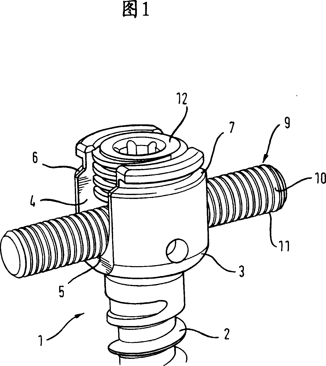
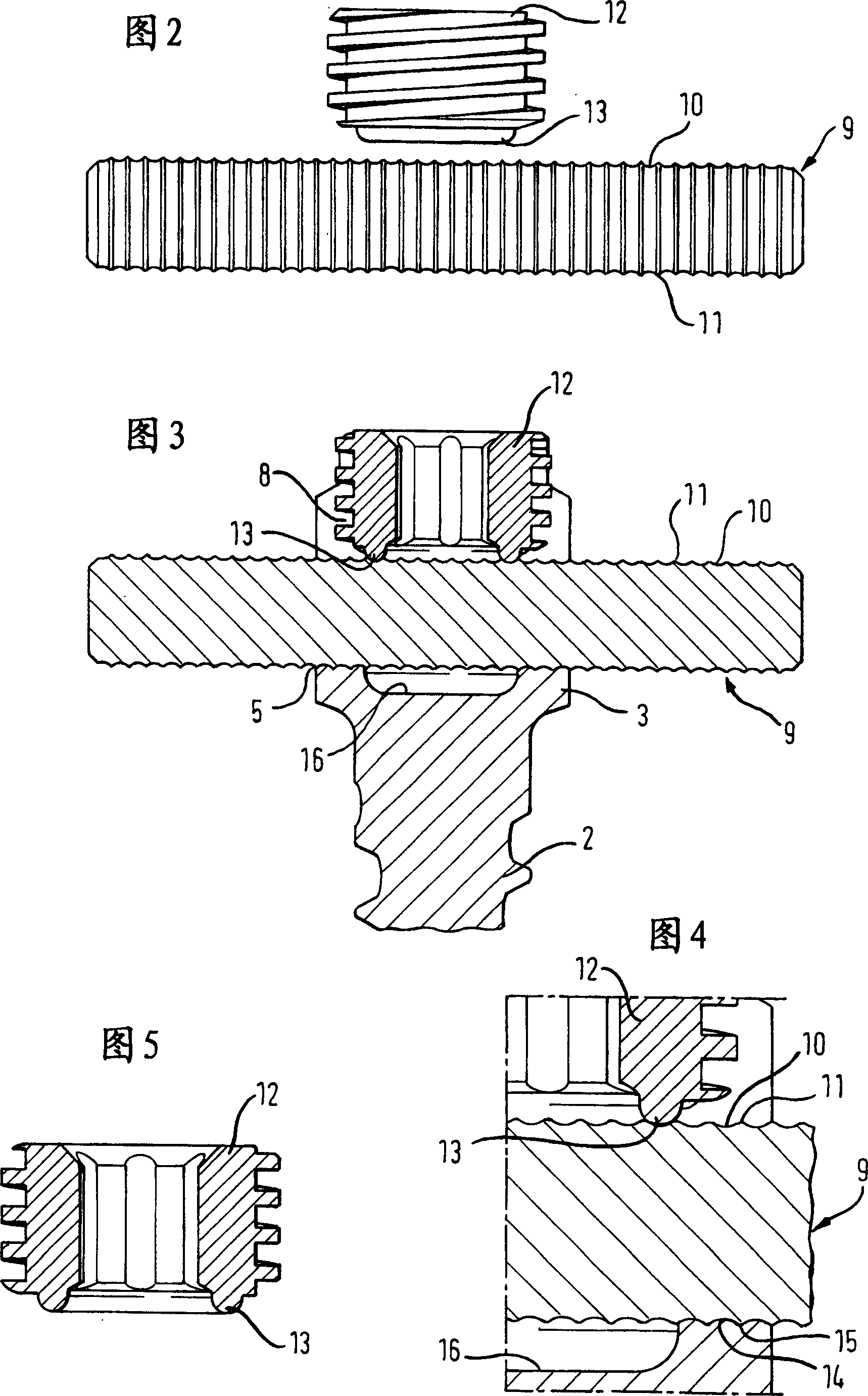
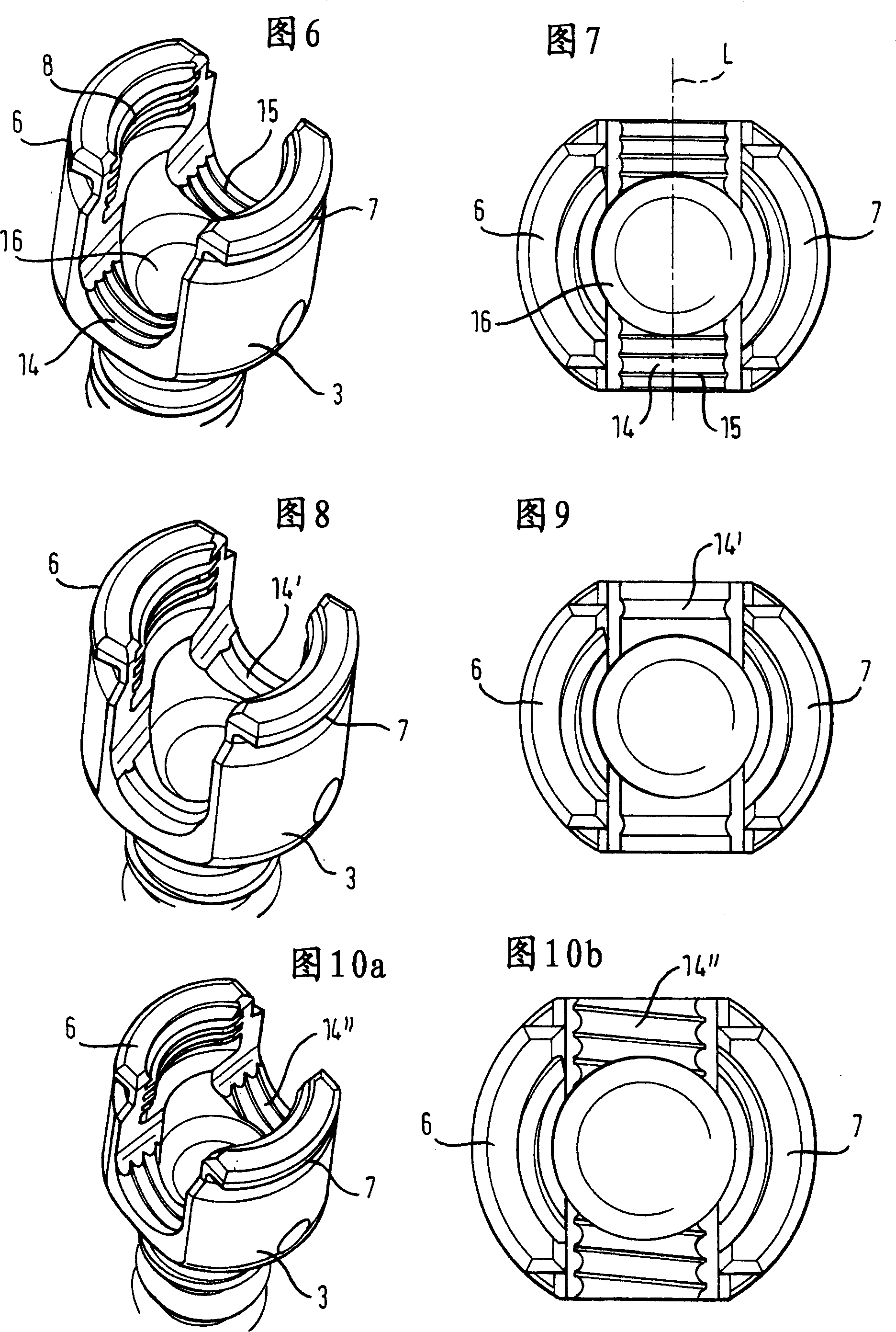
[0029] The first embodiment of the bone anchoring assembly shown in FIGS. 1 to 7 comprises a bone anchoring element 1 having a threaded anchor rod 2 and a receiving portion 3 . Said receiving part 3 is generally cylindrical and has a U-shaped recess 4 with a bottom 5 on the side of the threaded anchor. Two free legs 6 , 7 are formed by means of the U-shaped recess 4 . The hole with the internal thread 8 is arranged in a groove formed by the U-shaped recess 4 and coaxially with the central axis of the threaded anchor 2 . The internal thread 8 may have any known thread shape. However, a flat or negative thread is advantageous because it prevents the legs 6 , 7 from spreading out.

[0030] The bone anchoring assembly also includes a longitudinal rod 9 with a structured surface. In the illustrated embodiment, the rod has a circular cross-section. The formation is of ratchet type, comprising a plurality of circumferential grooves 10 separated by circumferential crests 11 .

[...


PUM


Abstract

A bone anchoring assembly for use in spinal surgery or trauma surgery is provided comprising an anchoring element (1) having a shaft (2) and a receiving part (3) having a substantially U-shaped cross-section with a base connected to said shaft and two free legs (6,7) forming a channel (4) for receiving a rod; a rod (9) having an at least partially structured surface (10, 11); a locking member (12) cooperating with the receiving part for locking said rod in the channel (4); wherein at least on the locking member (12) or in the receiving part an engagement portion (13; 14, 15) for engaging said structured surface (10, 11) of the rod is provided; characterized in that the locking member, the rod and the receiving part cooperate in such a manner that as soon as the engagement portion comes into engagement with the structured surface the rod is held in the receiving part in a form-locking manner preventing movement of the rod.

Description

technical field [0001] The present invention relates to a bone anchoring assembly used in spinal surgery or trauma surgery. In particular, the invention relates to a bone anchoring assembly comprising at least two bone anchoring elements with receiving portions for receiving rods connecting the bone anchoring elements, wherein the rods form a locked connection by means of fixed in the receiving part. Background technique [0002] US 5,207,678 discloses a pedicle screw comprising a screw and a receiving part for connecting the screw and a rod. The rod is a threaded rod which is locked in the receiving part by means of two nuts which engage on the outside of the receiving part and which are adjustable on the threaded rod. In order to readjust the position of the rod relative to the receiving part, the nut is turned on the threaded rod. This process is time consuming because both nuts must always be adjusted. [0003] US 5,443,467 discloses a bone anchoring assembly compris...

Claims


Application Information

Patent Timeline
Patent Type & Authority Applications(China)
IPC IPC(8): A61B17/70
CPCA61B17/7037A61B17/7002A61B17/7004A61B17/7005A61B17/7032A01K49/00A01K57/00
Inventor 于尔根·哈姆斯威尔斯里德·马蒂斯黑尔玛·拉普卢茨·比德尔曼
Owner BIEDERMANN TECH GMBH & CO KG
Why Eureka
Try Eureka