
Wear edge assembly

a technology of wear member and wear member, which is applied in the direction of soil shifting machine/dredger, construction, etc., can solve the problems of wear member loss, lock loosening, and wear member loosening, so as to facilitate easy removal of lock, resist loosening, and effective tighten the fit of wear member on the lip

Inactive Publication Date: 2007-02-01
ESCO CORP
View PDF99 Cites 7 Cited by
  • Summary
  • Abstract
  • Description
  • Claims
  • Application Information

AI Technical Summary

Benefits of technology

[0009] In one aspect of the invention, the wear assembly includes a lock for securing the wear member in place that is provided with improved means for tightening the fit of the wear member onto the lip and retaining the lock in the assembly during use. With the improved means, the lock is able to effectively tighten the fit of the wear member on the Lip, resist loosening of the fit, and facilitate easy removal of the lock without a concomitant increased risk of lock ejection.
[0010] In accordance with one aspect of the invention, the lock has a threaded take-up element that tightens the wear member onto the lip and includes means to inhibit loosening during use. A tighter fit results in reduced wear in the components. In one preferred embodiment, the take-up element includes a threaded member and a resilient member. The resilient member resists loosening of the threaded member and applies an expanding force that continues to tighten the fit of wear member on the protected structure even after wear begins to develop in the components. In addition, the threaded member provides a firm stop that resists overloading and lock ejection. In another construction, a threaded take-up member has an area of deformed threads to prevent inadvertent loosening of the take-up element.
[0011] In accordance with another aspect of the present invention, an arcuate path is used to effectively retain the lock and yet stilt permit easy release when replacement of the wear member is needed. In one embodiment, a lock body defines an arcuate path for receipt of a resilient latch member. The arcuate path enables the latch to be retracted into an open space free of impacted fines. In another embodiment, the wear member defines an arcuate path for receipt of an arcuate lock. The arcuate path inhibits pin ejection, but still permits easy removal of the lock with a hammer.
[0012] In accordance with another aspect of the invention, the lock utilizes a resilient take-up element and a resilient latch in a construction that provides continued tightening without an increased risk of lock ejection. In one embodiment, an arcuate lock is fit in an arcuate path. The lock includes an elastomeric body as the take-up element to tighten the wear member on the lip. In this way, the elastomeric body can apply a continued tightening force, and the rigid lock body in the arcuate path inhibits pin ejection.
[0013] In accordance with another aspect, a shroud or other wear member adapted to overlie the front digging edge of a bucket lip includes an arcuate passage which opens on both ends in an upper, exterior surface of the wear member for receiving a lock. The elimination of a large opening for receiving the lock increases the strength of the wear member. Moreover, the arcuate passage facilitates easy insertion and removal of the Lock with a hammer.

Problems solved by technology

Excavating buckets and other excavating equipment are typically subjected to harsh conditions.
However, under load, the legs of the wear member can shift and cause loosening of the lock and possible loss of the wear member.
In addition, the formation of a hole in the lip weakens the lip and lessens its ability to effectively resist large loads as it is forced into the ground.
However, the elastomer does not possess sufficient strength for the lock to well withstand the expected loads.
Hence, the wear member can shift during use, which may result in ejection of the lock and loss of the wear member.
While the use of a rigid member instead of an elastomeric body avoids overloading the lock during use, it does not provide any ability to tighten the mounting of the wear member on the lip.
However, the threaded plug can loosen during use in some circumstances due to vibration and impact forces.
Moreover, the lateral latch construction used in both this patent as well as the '214 patent, can at times be difficult to release on account of fines being impacted in the expansion space for the elastomer.

Method used


Image

  • Wear edge assembly
  • Wear edge assembly
  • Wear edge assembly

Examples


Embodiment Construction

[0042] The present invention pertains to an assembly for securing a wear member to a structure subjected to an abrasive work environment. The inventive wear assembly is particularly suited for protecting an edge of a structure, such as a digging edge of an excavating bucket.

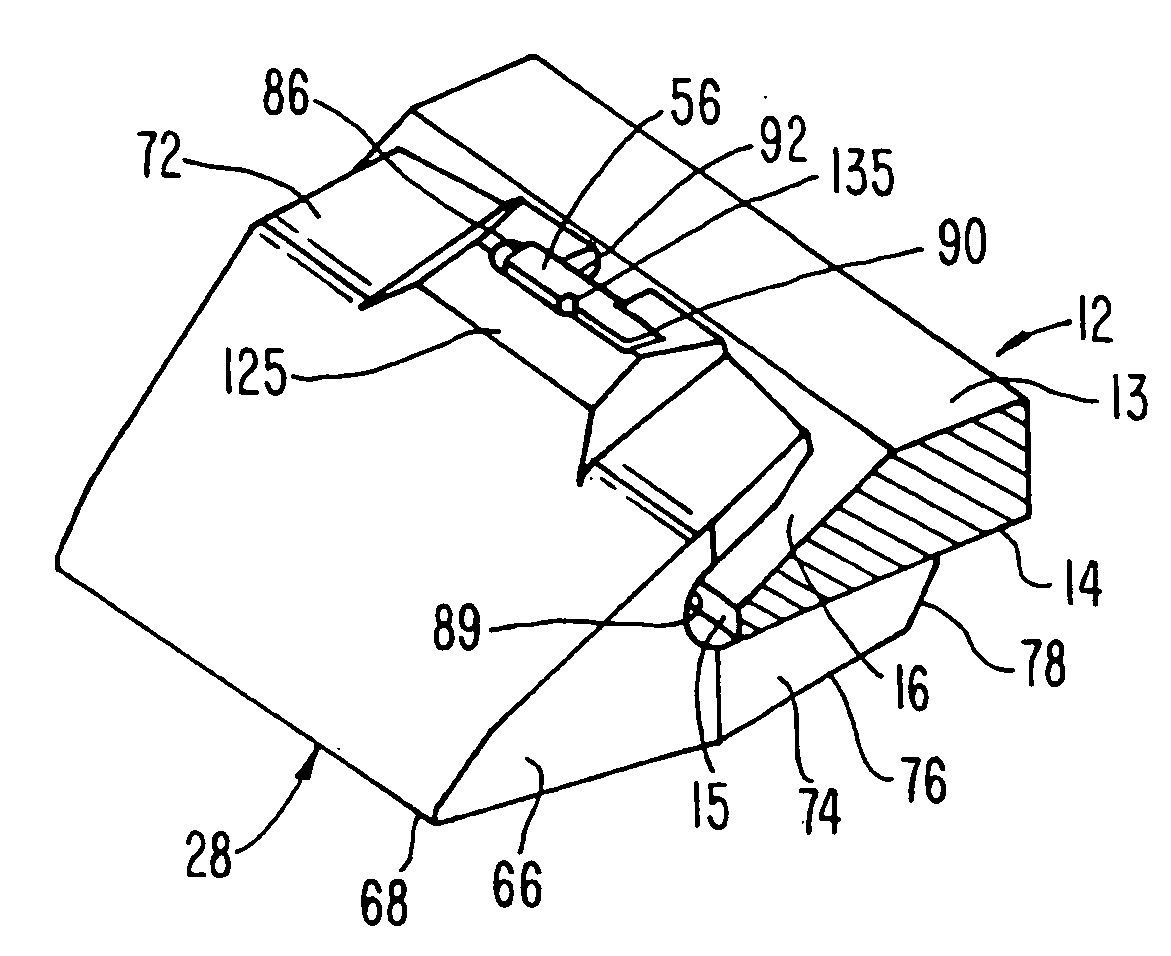
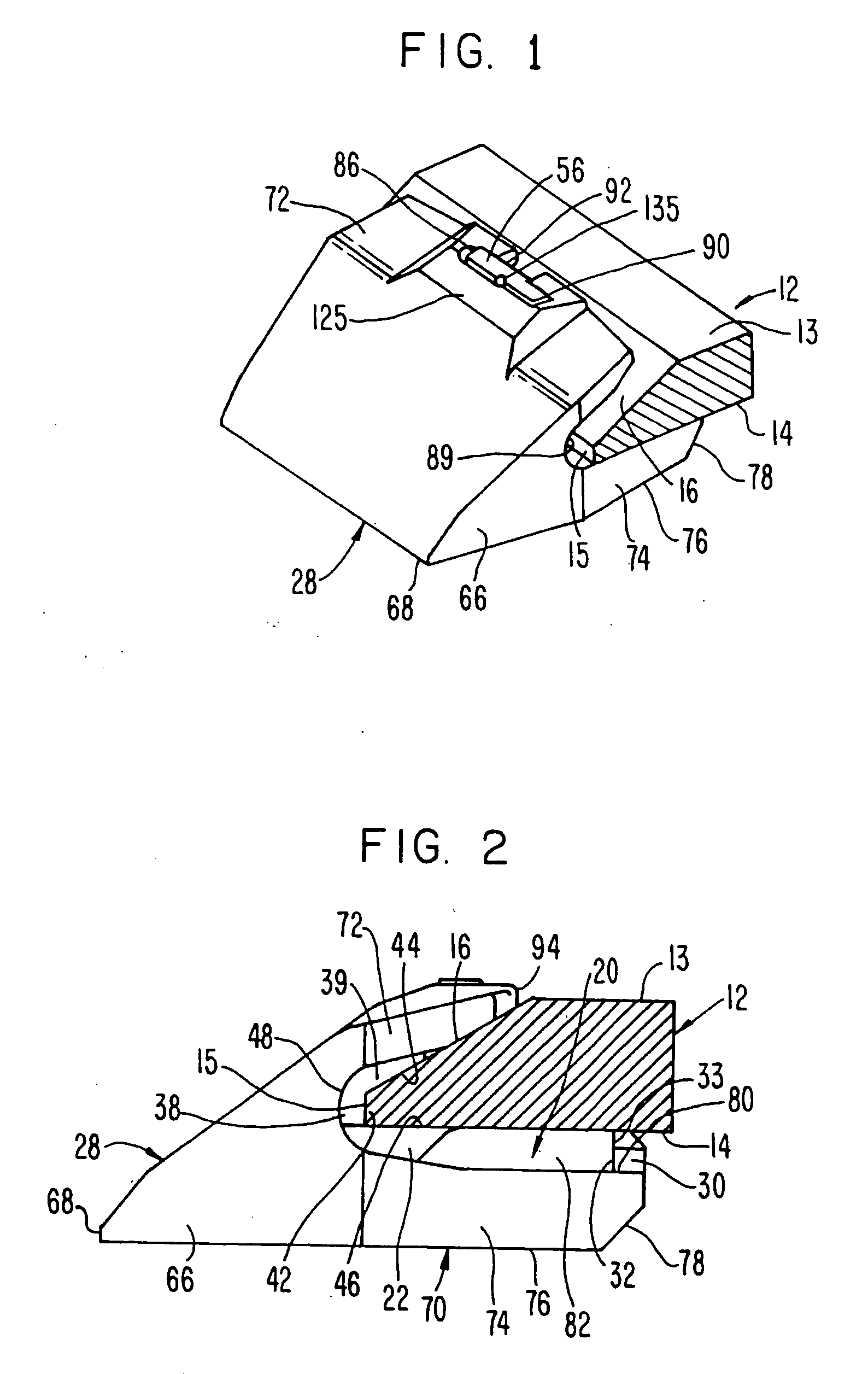
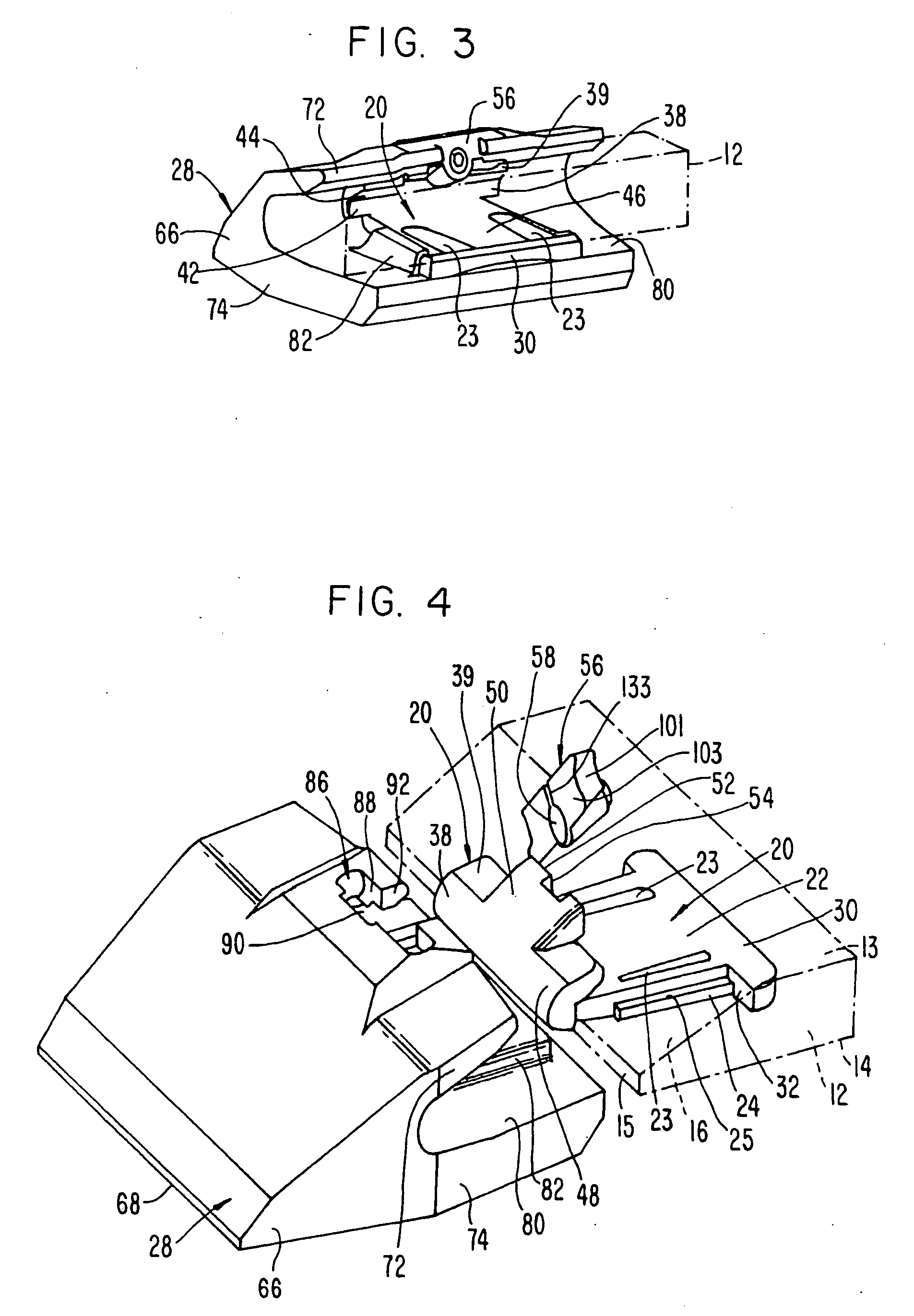
[0043] In a preferred construction, the wear member is a shroud that overlies and protects the front digging edge of an excavating bucket lip 12. The tip includes an inner face 13, an outer face 14 and a front edge face 15 (FIGS. 1 and 2). White the illustrated tip includes an interior ramp surface 16, the invention can be used with other kinds of lips. Moreover, the inventive concepts can be used to secure other kinds of wear members to other excavators.

[0044] The invention is at times discussed in terms of relative terms, such as up, down, vertical, horizontal, etc. for the sake of easing the description. These terms are to be considered relative to the orientation of the elements in FIG. 1 (unless otherwise ...


PUM


Abstract

A wear assembly for protecting a structure, such as an excavating bucket, from wear includes a lock for securing the wear member in place. The lock includes a take-up element for tightening the fit of the wear member, a latch to retain the lock in the assembly during use, and an arrangement for resisting loosening of the lock. With the assembly, the lock is able to effectively tighten the fit of the wear member on the lip, resist loosening of the fit, and facilitate easy removal of the lock without a concomitant increased risk of lock ejection.

Description

FIELD OF THE INVENTION [0001] The present invention pertains to a wear assembly for protecting a structure subjected to an abrasive environment. In a preferred construction, the inventive wear assembly is particularly suited for protecting the digging edge of an excavator, such as an excavating bucket. BACKGROUND OF THE INVENTION [0002] Excavating buckets and other excavating equipment are typically subjected to harsh conditions. A series of wear members are usually provided to protect the digging edge and other portions of the bucket from premature wear. Wear members have in the past been secured to the bucket in many different ways. [0003] For example, in U.S. Pat. No. 4,570,365 to Bierwith, the wear members are secured to the lip of the bucket through the use of a wedge and spool lock arrangement that is fit through a hole in the lip spaced from the front edge. In this arrangement, the spool pinches the rear ends of the wear member against the inner and outer faces of the lip as ...

Claims


Application Information

Patent Timeline
Patent Type & Authority Applications(United States)
IPC IPC(8): E02F9/28
CPCE02F9/2825E02F9/2883E02F9/2841E02F9/28E02F9/00
Inventor JONES, LARREN F.JONES, DAN
Owner ESCO CORP
Learn More