Mechanical system equipped with active microcapsules for condition monitoring

a technology of condition monitoring and mechanical system, applied in the field of mechanical system, can solve the problems of grease deterioration, rapid deterioration, failure of components, etc., and achieve the effect of evaluating the extent of wear or efficiency

Active Publication Date: 2015-11-12
AB SKF
View PDF0 Cites 1 Cited by
  • Summary
  • Abstract
  • Description
  • Claims
  • Application Information

AI Technical Summary

Benefits of technology

[0009]In accordance with the invention, the mechanical system also comprises microcapsules forming a shell which, due to changes in a given characteristic physical parameter of the mechanical system, is capable of releasing particles, the dispersion of which is identifiable by means external to the mechanical system. The mechanical system comprises a plurality of microcapsule types, each type of microcapsule being sensitive to the variation of a different physical parameter that is specific to the mechanical system, thus enabling the release of particles for the variations of different parameters.
[0010]Owing to the invention, by adapting the shell of the microcapsules to the physical parameter for which the variation is to be detected, and by adapting the particles to the type of identification desired, it is possible to monitor the condition of the mechanical system in relation to a given physical parameter. The parameterization of the shell in relation to a threshold value of a variation of said physical parameter thus enables the release of particles at this value, for example a value signifying a failure.
[0011]As these released particles are identifiable by a means external to the mechanical system, it can thus be possible to detect the appearance of a system failure in real time, during operation, without having to wait for a possible maintenance operation.
[0012]It is also possible to monitor changes of a parameter of the system over time and thus evaluate the extent of wear or efficiency during system operation, thereby enabling a possible maintenance operation to be anticipated or postponed.

Problems solved by technology

Faulty lubrication generally results in rapid deterioration and the failure of the components, and thus the system.
However, over time, the mixing of the lubricant combined with its aging and the heating cycles to which the components are subjected, causes the grease to deteriorate.
However, these maintenance operations must sometimes be anticipated in the event of abnormal deterioration or failure of a component of the mechanical system or its lubrication.
All these elements represent additional system costs, for which condition monitoring is complex to implement.

Method used


Image

  • Mechanical system equipped with active microcapsules for condition monitoring
  • Mechanical system equipped with active microcapsules for condition monitoring

Examples


Embodiment Construction

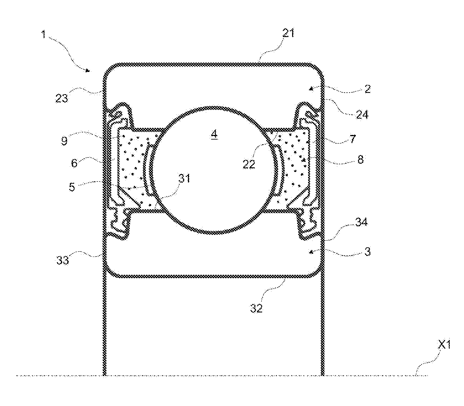
[0039]A bearing 1 with central axis X1 comprises an outer ring 2, an inner ring 3, a row of rolling elements 4, here balls, arranged in parallel planes held by a cage 5, and two seals 6 and 7, respectively.

[0040]The rings 2, 3 are coaxial with the central axis X1 in the normal operating mode.

[0041]The outer ring 2 comprises an outer cylindrical surface 21, a bore 22 wherein a raceway is formed for the rolling elements 4 and the grooves wherein are fitted the seals 6 and said seals form a static seal with the rotating outer ring 2.

[0042]The inner ring 3 comprises an outer cylindrical surface 31 wherein is formed a raceway for the rolling elements 4 and grooves for making contact seals with the seals 6 and 7, said seal forming a dynamic seal with the non-rotating inner ring 3.

[0043]Alternatively, the inner ring 3 may be rotating and the outer race 2 non-rotating, or both rings can be rotating relative to each other.

[0044]The outer ring 2 is defined axially by two frontal radial edges ...


PUM

PropertyMeasurementUnit
sizeaaaaaaaaaa
sizeaaaaaaaaaa
sizeaaaaaaaaaa

Abstract

A mechanical system comprising at least one moving component and a lubricant. The mechanical system also comprises a plurality of at least one type of microcapsule consisting of a shell, which, under the effect of a variation of a given characteristic physical parameter of the mechanical system, is capable of releasing particles. The dispersion of the particles is identifiable by a system located external to the mechanical system.

Description

CROSS REFERENCE TO RELATED APPLICATIONS[0001]This is a Non-Provisional Patent Application, filed under the Paris Convention, claims the benefit of France Patent (FR) Application Number 1401031 filed on 6 May 2014 (06.05.2014), which is incorporated herein by reference in its entirety.FIELD OF THE INVENTION[0002]The present invention concerns the field of mechanical systems with moving components, bearings for example, and for all types of applications requiring such systems, such as motorized vehicles, internal combustion engines, electric motors, and torque transmission elements, etc.PRIOR ART[0003]The service life of a mechanical system with moving components is essentially associated with the lubrication of the components. Faulty lubrication generally results in rapid deterioration and the failure of the components, and thus the system. Mechanical systems habitually comprise surfaces in mechanical contact which can be lubricated by a lubricant, grease or oil for example, initiall...

Claims


Application Information

Patent Timeline
Patent Type & Authority Applications(United States)
IPC IPC(8): F16C33/66C10M109/00F16C41/00
CPCF16C33/6688F16C2233/00C10M109/00F16C41/008F16C33/6659F16C33/6696F01M9/02F16C19/06F16C19/52F16C19/525F16C33/1045F16C33/109C10M171/00C10N2040/02C10N2050/12
Inventor BERENS, FRANKVARNOUX, LAURENTVERBE, OLIVIER
Owner AB SKF
Why Eureka
Try Eureka