Large-bearing-capacity large-stroke towing-shell type push rod with built-in functional motor
A technology of large stroke and push rod, applied in the field of electric push rod, can solve the problems of large volume, limited single-layer stroke, and motor occupying travel space, etc., and achieves the effect of compact size, good waterproofness and reasonable configuration.
- Summary
- Abstract
- Description
- Claims
- Application Information
AI Technical Summary
Problems solved by technology
Method used
Image
Examples
Embodiment 1
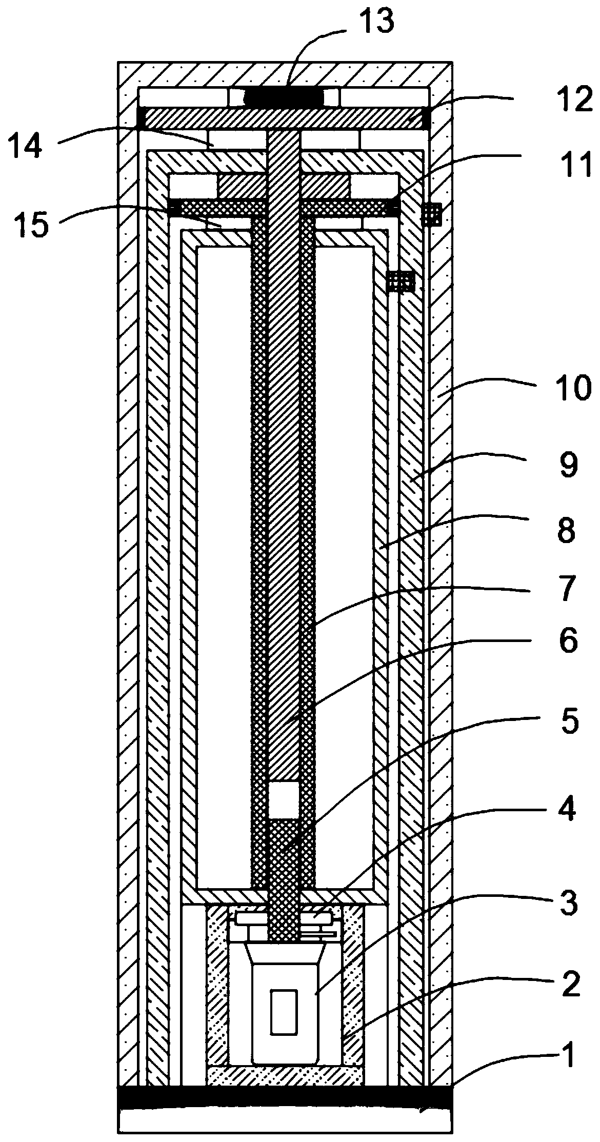
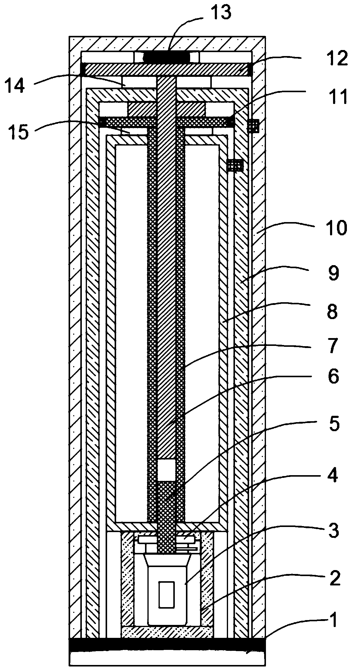
[0027] Such as figure 1 As shown, this embodiment provides a functional motor built-in high-load and large-stroke push rod, including a base 1 and a driving mechanism arranged on the base 1, and the base 1 is provided with multiple layers of push rods that are sequentially sleeved The power transmission telescopic assembly, the driving mechanism is nested inside the push rod power transmission telescopic assembly and drives the push rod power transmission telescopic assembly up and down, and the driving mechanism adopts an embedded functional motor (or geared motor).
[0028] In this embodiment, the function motor built-in high-load and large-stroke push rod is suitable for various complex or simple technological processes, and has the advantages of structure, convenient installation, reliable use, simple maintenance, and energy saving. Compared with the hydraulic and pneumatic system, it not only saves the complicated system and reduces the weight, but also is not limited by ...
Embodiment 2
[0032] This embodiment is further optimized on the basis of embodiment 1, specifically:
[0033]The push rod power transmission telescopic assembly is a two-layer push rod power transmission telescopic assembly, and the push rod power transmission telescopic assembly includes a first layer of push rod assembly 10 and a first layer of push rod assembly 10 Inside the second layer of push rod assembly 9, the second layer of push rod assembly 9 is provided with an inner support sleeve 8 located above the drive mechanism 2, and the inner center of the inner support sleeve 8 is provided with a second layer of hollow transmission rod 7. The upper end of the first layer of hollow transmission rod 7 extends out of the inner support sleeve 8 and is fixedly connected with the second layer of push rod threaded sleeve 11. The second layer of push rod threaded sleeve 11 is threaded with the inner wall of the second layer of push rod assembly 9. 7. There is a first-layer transmission shaft 6...
Embodiment 3
[0041] This embodiment is further optimized on the basis of embodiment 1, specifically:
[0042] A flat pressure bearing A14 sleeved on the transmission shaft 6 of the first layer is arranged below the first layer of push rod threaded sleeve 12, and the flat pressure bearing A14 is located above the push rod assembly 9 of the second layer. The flat pressure bearing B15 set on the second layer of hollow transmission rod 7 is arranged under the threaded sleeve 11 of the push rod. The flat pressure bearing B15 is located above the inner support sleeve 8, and the inner top of the independent support protection frame 2 is set There is a flat pressure bearing C4 sleeved on the output shaft 5 of the motor 3 .
[0043] The outer wall of the second layer push rod assembly 9 is provided with an anti-rotation protruding block (or bar), and the inner wall of the first layer of push rod assembly 10 is provided with an anti-rotation protruding block (or bar). The anti-rotation groove, the ...
PUM
 Abstract
Description
Claims
Application Information
 - R&D
- Intellectual Property
- Life Sciences
- Materials
- Tech Scout
- Unparalleled Data Quality
- Higher Quality Content
- 60% Fewer Hallucinations
Browse by: Latest US Patents, China's latest patents, Technical Efficacy Thesaurus, Application Domain, Technology Topic, Popular Technical Reports.
© 2025 PatSnap. All rights reserved.Legal|Privacy policy|Modern Slavery Act Transparency Statement|Sitemap|About US| Contact US: help@patsnap.com


