Exercise apparatus

Inactive Publication Date: 2000-03-28
NORTON DAVID A
View PDF14 Cites 65 Cited by
  • Summary
  • Abstract
  • Description
  • Claims
  • Application Information

AI Technical Summary

Problems solved by technology

Moreover, if some sort of lubrication were used on the pole carriage tr

Method used


Image

  • Exercise apparatus
  • Exercise apparatus
  • Exercise apparatus

Examples


Embodiment Construction

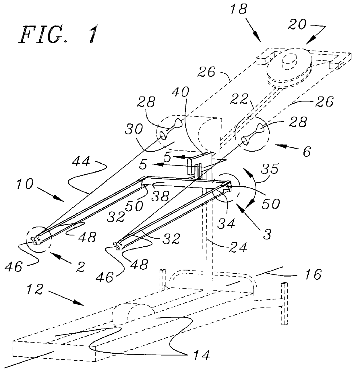
Preferred apparatus of the invention 10 is depicted in FIG. 1 attached to a well known cross-country skiing-simulative exercise device 12 of the sort manufactured by NordicTrack Corporation of Chaska, Minn. As is known in the art, such ski treadmills provide various means (such as foot trolleys (not shown)) engaged by an exerciser's feet and moved back and forth on respective tracks 14 disposed parallel to and on either side of a longitudinal axis 16 of the machine to simulate motion of cross-country skis over snow. It is noted that the present invention is concerned with apparatus for providing enhanced arm exercise when using a ski treadmill, is compatible with various known arrangements for engaging the exerciser's feet, and is not limited to use with any particular one of them.

Skiing-simulative equipment 12 of interest comprises a means 18 for resisting a rearward pulling force imposed by either of the exerciser's arms. That is, when the exerciser moves his or right foot forward...


PUM


Abstract

Apparatus that can be added to an existing ski treadmill provides resistance to a forward, as well as a rearward motion of an exerciser's arm. The apparatus includes a transverse beam attached to a body supporting post that is part of the treadmill. Longitudinal arms are hinged to the ends of this beam and swing away from their normal operating positions to allow an exerciser to mount or dismount from the apparatus. A closed rope loop having an indented portion is formed by connecting the two handgrips of a conventional ski treadmill with another piece of rope that engages, in sequence, a first pulley at the rear end of a first of the longitudinal arms, a second pulley near a hinge connecting that arm to the transverse beam, a third pulley at the other end of the beam, and a fourth pulley at the rear end of the second longitudinal arm.

Description

Not ApplicableNot Applicable1. Field of the InventionAn improved exercise machine simulative of cross-country skiing is provided by the invention.2. Background InformationSki treadmills, exercise machines that allow a user to simulate the motions involved in cross-country skiing, have been popular for many years. Perhaps the best known machines of this sort are made by the NordicTrack Corporation of Chaska, Minn. Examples of the variety of machines made by that firm, or for apparent use with their equipment, can be found in the patent art and include:U.S. Pat. No. 5,533,952, to Shaber, who uses a handgrip with multiple anchor points in order to vary the muscles being exercised.U.S. Pat. No. 5,387,168, to Bostic, describes adding a waist belt to a NordicTrack ski treadmill.U.S. Pat. No. 4,728,102, to Pauls, shows a load indicator used with this sort of apparatus.U.S. Des. Pat. Nos. 351,435 and 335,908 show two cosmetic designs for a ski treadmill.U.S. Pat. No. 5,762,584 shows an elec...

Claims


Application Information

Patent Timeline
IPC IPC(8): A63B23/12A63B23/035A63B69/18
CPCA63B22/0002A63B22/205A63B69/182A63B2022/0005A63B22/0005
Inventor NORTON, DAVID A.
Owner NORTON DAVID A
Why Eureka
Try Eureka