Optical node in an optical bus network

a technology of optical bus network and optical node, which is applied in the direction of multiplex communication, wavelength-division multiplex system, instruments, etc., can solve the problems of network normally having an unnecessarily large amount of wavelength channels, and over-dimensioning,

Inactive Publication Date: 2000-04-11
TELEFON AB LM ERICSSON (PUBL)
View PDF9 Cites 18 Cited by
  • Summary
  • Abstract
  • Description
  • Claims
  • Application Information

AI Technical Summary

Problems solved by technology

However this type of interruption actuates the communication between the different nodes and involves one or more receivers and transmitters in each node having to change such that it receives or sends, respectively, a wavelength channel via some of these reserve fibres.
Since the same channel is consequently used many tim

Method used


Image

  • Optical node in an optical bus network
  • Optical node in an optical bus network
  • Optical node in an optical bus network

Examples


first embodiment

FIG. 2 shows the optical node according to the invention; and

second embodiment

FIG. 3 shows the optical node according to the invention.

PREFERRED EMBODIMENTS

The invention will now be described in greater detail with reference to the Figures and in particular to FIG. 2 and FIG. 3 which show two different embodiments of the optical node according to the invention.

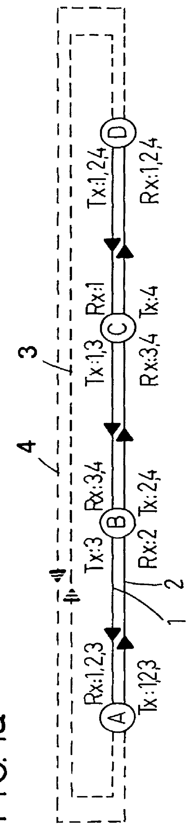
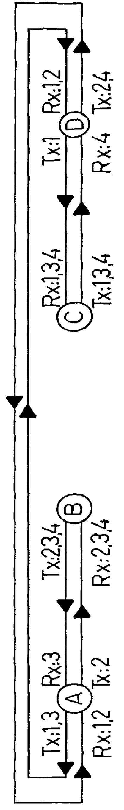
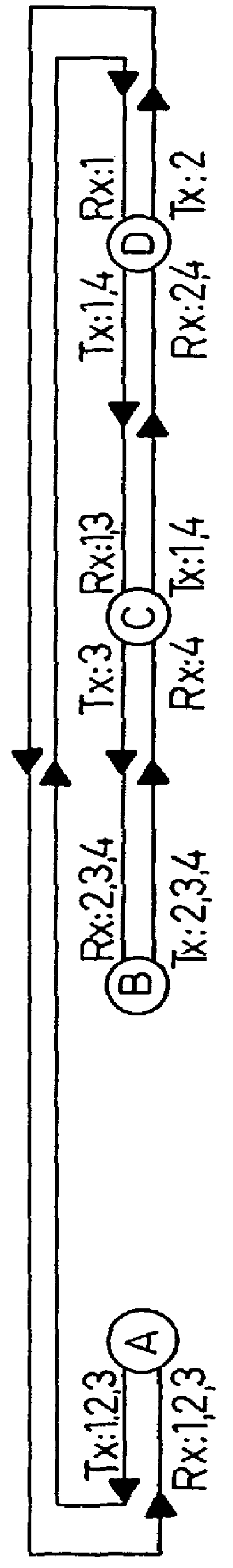
FIGS. 1a-c show an optical bus network which has four nodes A, B, C, D and is provided with an extra fibre pair 3, 4 which can be used in the case of an interruption in the regular bus network. Each node comprises three transmitters and three receivers. Depending on where in the network the node is located, a varying number of transmitters Tx:1-4 and receivers Rx:1-4 are connected to the first fibre 1. A first node A, for example, has three receivers Rx:1-3 connected to the fibre 1, all of whose signals go towards the left in the Figures, and three transmitters Tx:1-3 connected to the fibre 2, all of whose signals go to the right in the Figures. On the other hand a final node D has three receivers Rx: 1...


PUM


Abstract

PCT No. PCT/SE96/00323 Sec. 371 Date Nov. 20, 1997 Sec. 102(e) Date Nov. 20, 1997 PCT Filed Mar. 13, 1996 PCT Pub. No. WO96/31025 PCT Pub. Date Oct. 3, 1996An optical node in an optical network includes transmitters (Tx:1-3) and receivers (Rx:1-3) adapted to particular wavelength channels and arranged to communicate via the optical bus network, with receivers and transmitters for corresponding wavelength channels in other nodes. The node includes optical safety switching devices (S1-S5) in connection with the transmitters (Tx:1-3) and receivers (Rx:1-3) of the node, so that the transmitters (Tx:1-3) and receivers (Rx:1-3) can be switched from a first optical fiber (1,2) to a second optical fiber (1,2).

Description

TECHNICAL BACKGROUNDThe present invention concerns an optical node in an optical bus network. The node comprises transmitters and receivers which are adapted to particular wavelength channels and are arranged to communicate via the optical bus network with receivers and transmitters for corresponding wavelength channels in other nodes.The invention also concerns a process carried out in an optical bus network.PRIOR ARTWithin the field of telecommunications, there is frequently a need for high transmission capacity. Large amounts of data can be transmitted very rapidly by using optical transmission via modulated light signals.Wavelength multiplexing (WDM) is used to transmit a plurality of light signals via a common optical medium. The signals are sent via independent wavelength channels which can be present simultaneously in an optical fibre.Optical transmission can be brought about in an optical bus network which comprises a plurality of optically connected nodes adapted for mutual...

Claims


Application Information

Patent Timeline
IPC IPC(8): H04J14/02H04B10/213H04B10/27H04B10/278
CPCH04B10/27H04B10/278H04J14/0212H04J14/0295H04J14/0246H04J14/025H04J14/0256H04J14/028H04J14/0219H04J14/0227H04J14/0268H04J14/02
Inventor OBERG, MAGNUS
Owner TELEFON AB LM ERICSSON (PUBL)
Why Eureka
Try Eureka