Noncontact IC device

a non-contact, ic card technology, applied in the direction of circuit security details, printed element electric connection formation, instruments, etc., can solve the problems of difficult to punch holes in ic cards, inability to prevent the dishonest sale of used non-contact ic cards wrapped in false envelopes similar in appearance to genuines, and difficult to distinguish between used and unused states of prepaid ic cards provided with terminals

Inactive Publication Date: 2000-06-13
DAI NIPPON PRINTING CO LTD
View PDF5 Cites 111 Cited by
  • Summary
  • Abstract
  • Description
  • Claims
  • Application Information

AI Technical Summary

Benefits of technology

The short-circuiting circuit may be formed entirely of a solder paste having electrical resistance which is reduced when the solder paste is melted and then solidified.

Problems solved by technology

It is difficult to discriminate between a used state and an unused state of a prepaid IC card provided with terminals, like a telephone card.
Therefore it is not easy to punch holes in IC cards and IC cards are not used as prepaid telephone cards.
The noncontact IC card may be wrapped in an envelope having an electromagnetic shielding effect to enable the discrimination between a used state and an unused state of the noncontact IC card from the condition of the envelope, which, however, is expensive and is incapable of preventing the dishonest selling of used noncontact IC cards wrapped in a false envelope similar in appearance to a genuine envelope at coupon shops.
The breaking part provided with the folding grooves 16 may accidentally be broken if the thickness of the breaking part is excessively small.

Method used


Image

  • Noncontact IC device
  • Noncontact IC device
  • Noncontact IC device

Examples


second embodiment

A noncontact IC card in a second embodiment according to the present invention will be described with reference to FIGS. 7 to 14(D), in which parts like or corresponding to those shown in FIGS. 1 to 6 are designated by the same reference characters and the description thereof will be omitted.

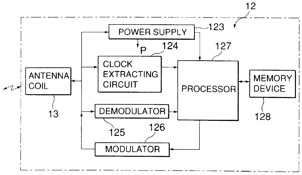
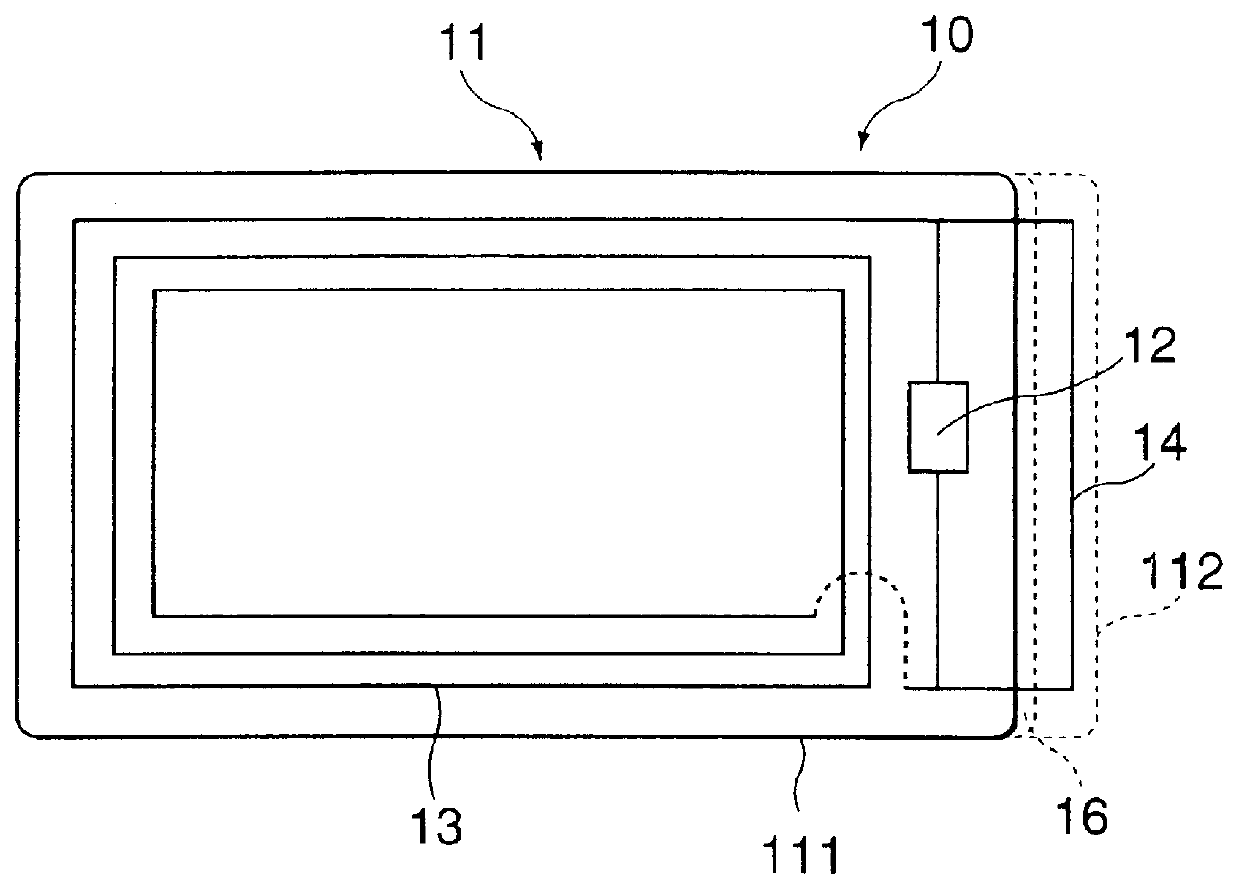
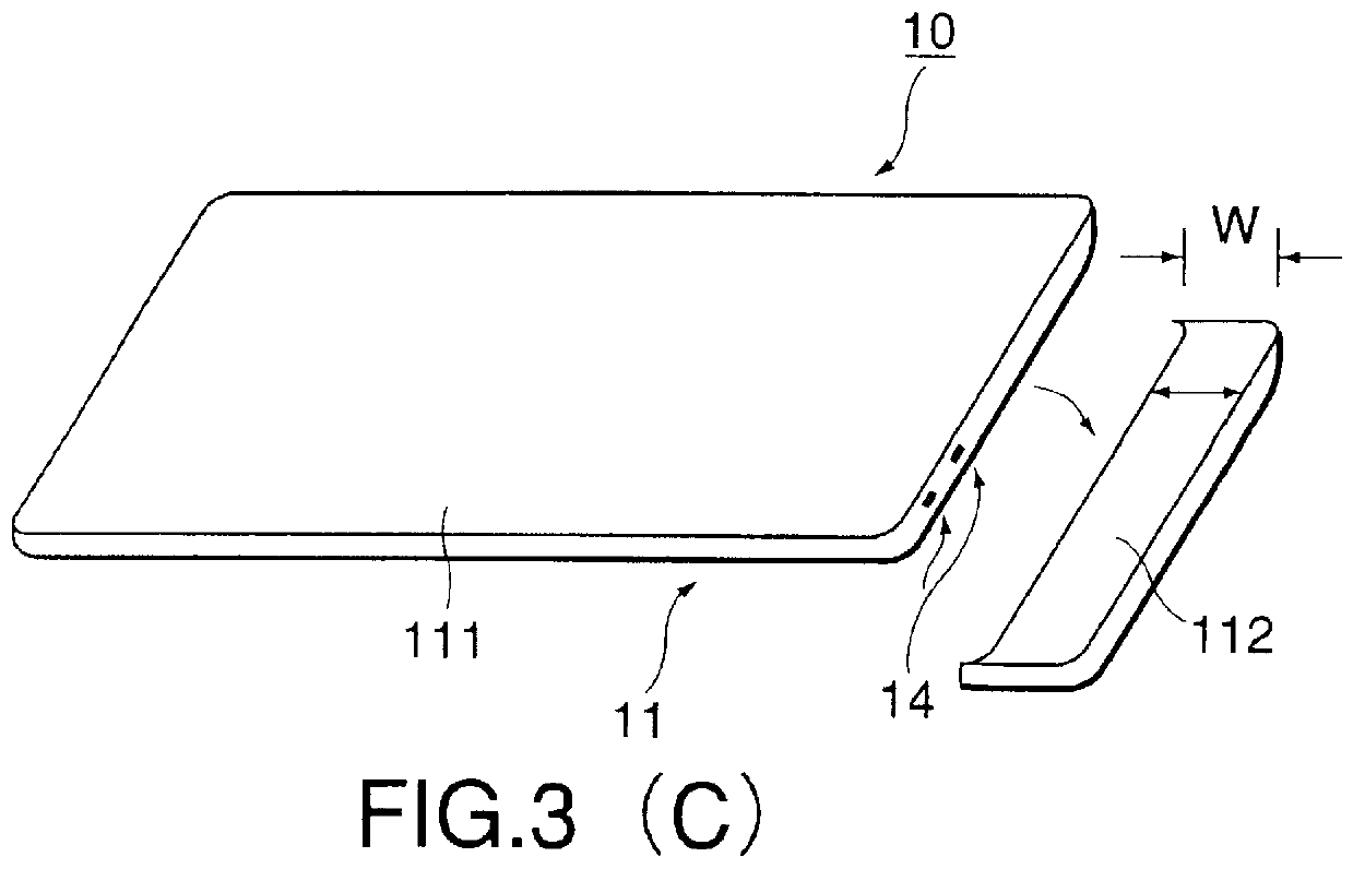
Referring to FIG. 7, a noncontact IC card 10, i.e., a noncontact IC device, in a second embodiment according to the present invention has a base card 11 having a main part 111, a removable identification part 112 and a breaking part provided with folding grooves 16 and connecting the main part 111 and the identification part 112. An IC chip 12 is mounted on the main part 111 of the base card 11, and an antenna coil 13 is formed on the main part 111.

The noncontact IC card 10 features a short-circuiting circuit 14 formed in one end of the main part 111 and the identification part 112, and connected to the opposite ends of the IC chip 12. The short-circuiting circuit 14 has a connecting part 17 hav...

example

An example of the noncontact IC card 10 will be described. It is presumed that thirty noncontact IC cards 10 are formed in five rows and six columns on a base sheet. Aluminum films of 20 .mu.m in thickness for forming the antenna coils 13, the short-circuiting circuit 14 and the connecting circuit 15 were formed on both the surfaces, respectively, of a 25 .mu.m thick polyethylene terephthalate film by an electroless plating process and a subsequent electroplating process. The aluminum film formed on the upper surface, i.e., a surface on which the IC chips 12 are to be mounted, was subjected to a photolithographic etching process to form the antenna coils 13 and the terminals 113a and 115a to which the IC chips 12 are to be connected. Each of the antenna coils 13 was formed by winding a 160 .mu.m wide line in four turns at intervals of 160 .mu.m on the middle sheet 11c of the base card 11. The short-circuiting circuits 14 and the connecting circuits 15 were formed by processing the a...


PUM


Abstract

A noncontact IC card is provided with an antenna coil, an IC chip and a short-circuiting circuit formed on a base card. The noncontact IC card is kept inoperative unless the short-circuiting circuit is opened and the noncontact IC card is rendered operative when the short-circuiting circuit is opened. The short-circuiting circuit is formed to extend across a main part and a removable identification part included in the base card. The short-circuiting circuit can be opened by removing the identification part from the base card.

Description

1. Field of the InventionThe present invention relates to a noncontact IC device, such as a noncontact IC card, capable of exchanging data with an external reader / writer in a noncontact communication mode and, more particularly, to a noncontact IC device capable of being easily changed from an unused state to a used state.2. Description of the Related ArtIC cards provided with terminals have prevalently been used particularly in France as prepaid telephone cards because of their high ability to prevent the dishonest alteration of information stored therein as compared with magnetic cards.It is difficult to discriminate between a used state and an unused state of a prepaid IC card provided with terminals, like a telephone card. Unused prepaid IC cards must be identified not only by coupon shops but also by purchasers.Prepaid telephone cards having 0.25 mm in thickness of a magnetic recording system are used in Japan. The start of use of this prepaid telephone card and an approximate ...

Claims


Application Information

Patent Timeline
Patent Type & Authority Patents(United States)
IPC IPC(8): G06K19/073G06K19/077H05K1/00H05K3/40
CPCG06K19/073G06K19/07749H05K1/0293G06K19/07726H01L2924/01322H01H2231/05H01L2224/16H01L2924/01057H01L2924/01078H01L2924/3025H05K1/0275H05K3/4084H05K2201/0305H05K2201/0909H05K2201/09127H05K2203/173H05K2203/175H01L2924/01019
Inventor TAKAHASHI, NORIO
Owner DAI NIPPON PRINTING CO LTD
Why Eureka
Try Eureka