Retention balloon for a corporeal access tube assembly

a technology for access tubes and retention balloons, which is applied in balloon catheters, medical science, surgery, etc., can solve the problems of difficult inserting and removal, easy breakage of silicone balloon walls, and difficult to insert and remov

Inactive Publication Date: 2000-06-20
CR BARD INC
View PDF36 Cites 94 Cited by
  • Summary
  • Abstract
  • Description
  • Claims
  • Application Information

AI Technical Summary

Problems solved by technology

However, they are unreliable because the silicone balloon walls, which are stretched thin when expanded, tend to break easily.
Preformed, molded internal retention devices must be deformed with a stylet and are difficult to insert and remove, although they are generally reliable once they are in place.
Second, the balloon is supported by trapped air at ambient pressure.

Method used


Image

  • Retention balloon for a corporeal access tube assembly
  • Retention balloon for a corporeal access tube assembly
  • Retention balloon for a corporeal access tube assembly

Examples


example 2

14 FRENCH

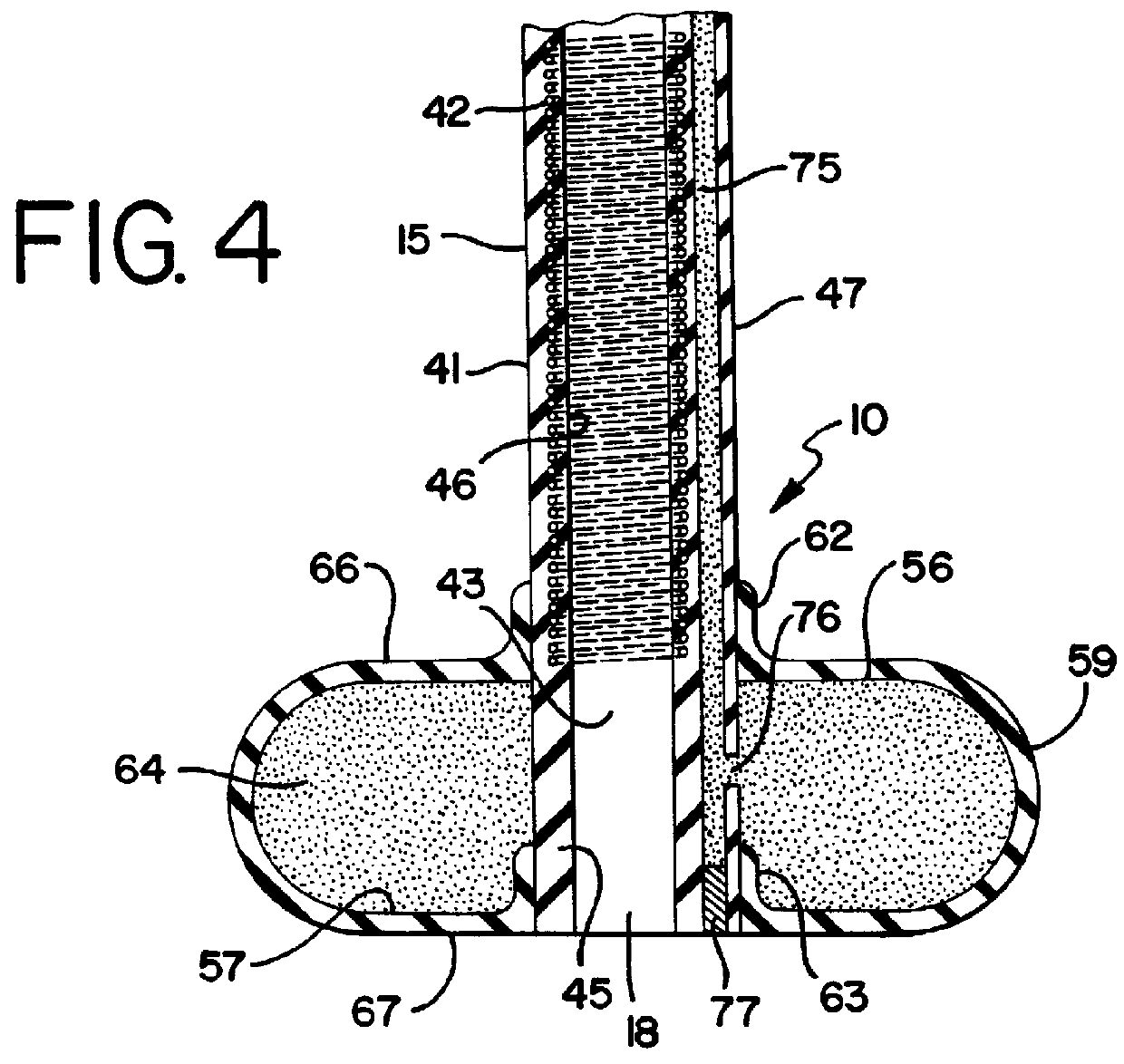
Referring to FIG. 7, a retention balloon 20 embodying features of the present invention is shown in its retention configuration on a 14 French tube segment 15. The 14 French tube has an outside diameter (O.D.) of 0.180 inches at its outer surface 47. The bead sleeves 62 and 63 on the balloon 20 each have corresponding inside diameters (I.D.). The O.D. of the balloon 20 is 0.712 inches.

In this balloon 20, the sidewalls 56 and 57 and the treadwall 59 are 0.020 inch thick silicone rubber film. The front sidewall bead sleeve 62 is 0.015 inches thick. The rear sidewall bead sleeve 63 is also 0.015 inch thick, however. The sleeve 63 extends 0.070 inches forwardly of the front wall 57. The sleeve 62 extends 0.065 inches forwardly of the rear wall 56.

In the balloon 20 of the invention combined with a 20 French tube segment 15 to form the assembly 10, the distance between the surfaces 66 and 67 is 0.250 inches. The radius of the semi-circular tread 59 on its outer surface is 0.125 i...


PUM


Abstract

An improvement in an internal bolster for a corporeal access tube assembly wherein a retention balloon is preformed of relatively thick silicone rubber film. The balloon includes parallel front and rear sidewalls connected by a semi-circular treadwall, the front sidewall having a front retention surface thereon with a radial width equal to the radius of the treadwall. Annular sleeves at the inner periphery of each sidewall are sealed to the outer surface of a tube segment. Each sleeve extends forwardly of its corresponding sidewall.

Description

This invention relates generally to medical catheters. It relates particularly to catheters used to access the stomach and / or intestine, or the bladder, through a stoma or ostomy in the abdominal wall.BACKGROUND OF THE INVENTIONSThe need to artificially introduce food into the gastrointestinal tracts of individuals who can not eat, or will not eat, has been well-known throughout and even prior to this century. Before the mid-1970's, feeding was done nasogastrically with red rubber or polyvinylchloride feeding tubes. The use of enteral feeding by means of nasogastric tubes expanded dramatically in the late 1970's with the introduction of tubes constructed of either silicone rubber or polyurethane. Being constructed of stronger materials, these tubes incorporated thinner walls, and were therefore smaller in outside diameter. These smaller tubes were easier to insert and more comfortable for the patient, and their introduction resulted in a very rapid growth of enteral nutrition via th...

Claims


Application Information

Patent Timeline
Patent Type & Authority Patents(United States)
IPC IPC(8): A61J15/00A61M25/00A61B17/34A61M25/10A61F2/958A61M25/04A61M25/095
CPCA61J15/0015A61M25/0067A61M25/04A61J15/0042A61B2017/3486A61M25/005A61M25/1002A61M2025/0233A61M2025/1065Y10S128/26A61J15/0061A61M25/10
Inventor QUINN, DAVID G.
Owner CR BARD INC
Why Eureka
Try Eureka