Wafer cassette load station

a cassette and load station technology, applied in the direction of packaging goods, charge manipulation, furniture, etc., can solve the problems of increasing the overall footprint of the system, manual handling, and limited wafer handling

Inactive Publication Date: 2000-07-04
APPLIED MATERIALS INC
View PDF14 Cites 109 Cited by
  • Summary
  • Abstract
  • Description
  • Claims
  • Application Information

AI Technical Summary

Problems solved by technology

Also, as the wafer size has increased, the handling of wafers has become more limited to factory automation, instead of manual handling, to accommodate the increase in size and weight of wafer pods.
Both the location of the door opener 42 and the horizontal motion required to remove the door consume additional floor space in the front-end staging area, thereby increasing the overall footprint of th

Method used


Image

  • Wafer cassette load station
  • Wafer cassette load station
  • Wafer cassette load station

Examples


Embodiment Construction

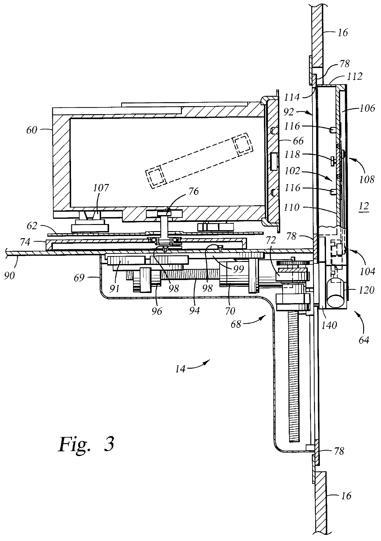
FIG. 3 is a cross sectional view of a pod loading station 14 of the invention having a wafer pod 60 disposed thereon. As used herein, the term pod refers to any container which holds one or more workpieces therein. The pod loading station generally includes a base plate 90 and an interface plate 78 which support a pod receiving platform 62 for supporting a wafer pod and a pod door opening mechanism 64 to engage and lower the pod door 66. An enclosure 68 defined by the base plate, the lower portion of the interface plate 78 and a cover 69 houses two actuators 70, 72 which are mounted to the base plate and the interface plate and which move the pod receiving platform 62 and the pod door opening mechanism 64 respectively. The interface plate 78 defines an opening 92 through which the wafer pod 60 moves to engage the door opening mechanism 64.

The receiving platform 62 is mounted on a translating platform 74 which is connected to the first actuator 70. The first actuator 70 which moves t...


PUM


Abstract

A pod loading station and method of operation are provided for enabling the transfer and introduction of wafers into a processing system from a wafer pod. The pod loading station generally includes a movable receiving platform for supporting a wafer pod and a movable pod door receiver having a pod door latch actuating mechanism disposed thereon. The movable platform supports a wafer pod, moves the wafer pod into engagement with the pod door receiver, and then retracts to enable the door supported by the door receiver to be removed from the opening of the pod. The pod door receiver then lowers the pod door below the pod to enable access to the pod opening.

Description

1. Field of the InventionThe present invention relates to an apparatus and method for loading wafers into a processing system. More particularly, the invention relates to a method and apparatus for accessing a wafer pod or cassette so that wafers can be moved between the wafer pod and the processing system.2. Background of the Related ArtThe fabrication of electronic devices on substrates is typically performed in processing systems. Processing systems take on various configurations including single wafer systems where a single wafer is processed in a processing chamber and batch type systems where multiple wafers are processed in a chamber. Despite system architecture disparities, substrates are delivered to the processing systems from a clean room using standardized interfaces and wafer pods or cassettes. A human operator or factory automation delivers multiple wafers loaded in wafer pods or cassettes to a loading mechanism which transfers the wafers from the clean room in a fabri...

Claims


Application Information

Patent Timeline
IPC IPC(8): H01L21/677H01L21/67B65G49/07
CPCH01L21/67772H01L21/67775Y10S414/137Y10S414/139H01L21/00
Inventor NERING, ERIC A.PERLOV, ILYAGANTVARG, EUGENEBELITSKY, VICTOR
Owner APPLIED MATERIALS INC
Why Eureka
Try Eureka