Hydraulic jack

a hydraulic jack and jack body technology, applied in the field of hydraulic jacks, can solve the problems of ineffective use of hydraulic jacks, high labor costs, and user troubles, and achieve the effects of reducing labor costs, reducing labor costs, and improving safety

Inactive Publication Date: 2000-07-11
LEE STEVEN
View PDF4 Cites 23 Cited by
  • Summary
  • Abstract
  • Description
  • Claims
  • Application Information

AI Technical Summary

Problems solved by technology

However, when the hydraulic jack of this type is not in use and the work on the object is finished, the user will have to disassemble the handle (62) from the hydraulic cylinder (61) and use the fork-like end of the handle (62) to rotate the release button (63) to release the pressure in the hydraulic cylinder (61), which is very troublesome for the user.
However, when the hydraulic jack of the type is about to turn to another direction, the user will have to lift up one side of the jack and move to the desired direction, which is ineffective in use of the jack and labor costly.

Method used


Image

  • Hydraulic jack
  • Hydraulic jack
  • Hydraulic jack

Examples


Embodiment Construction

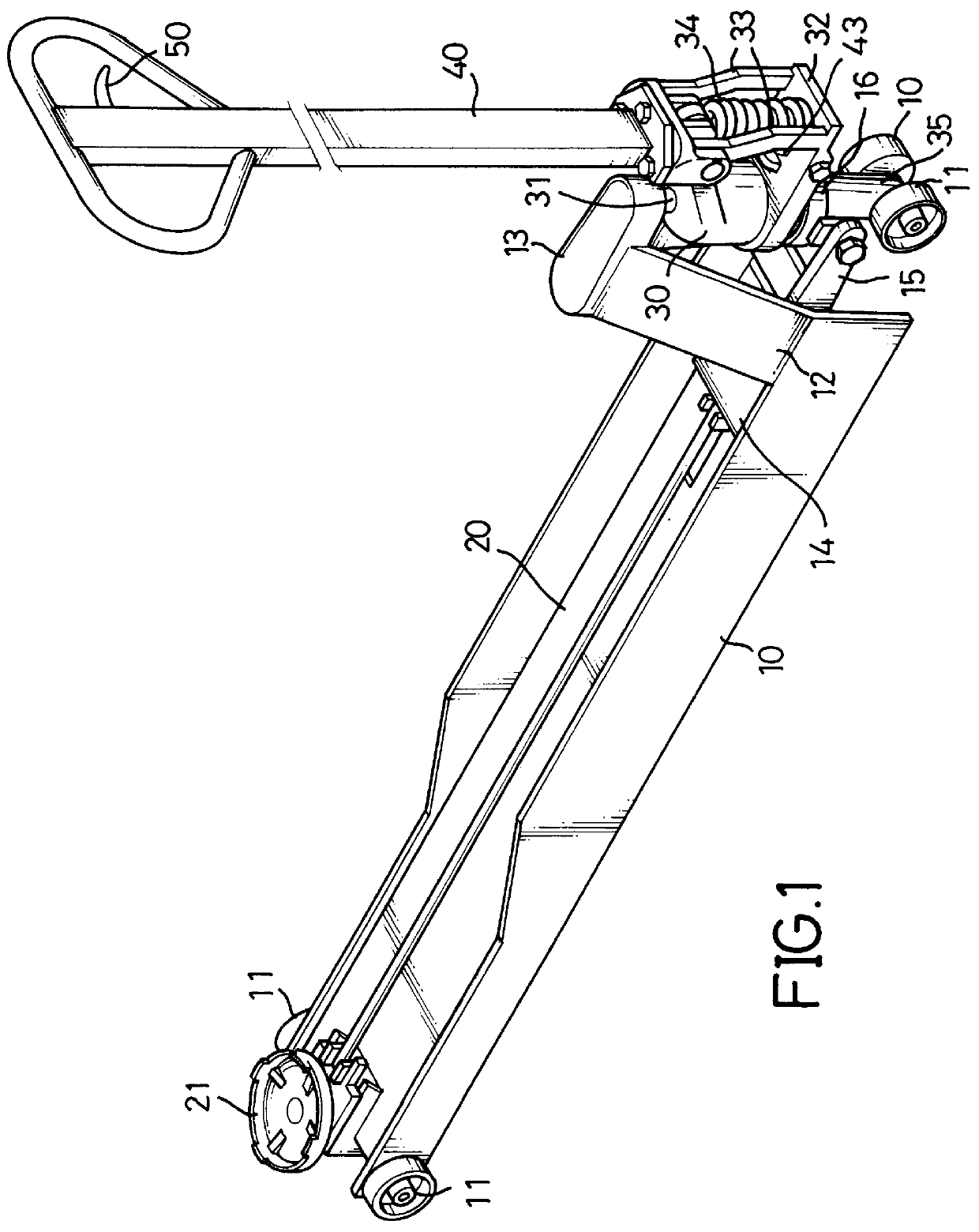
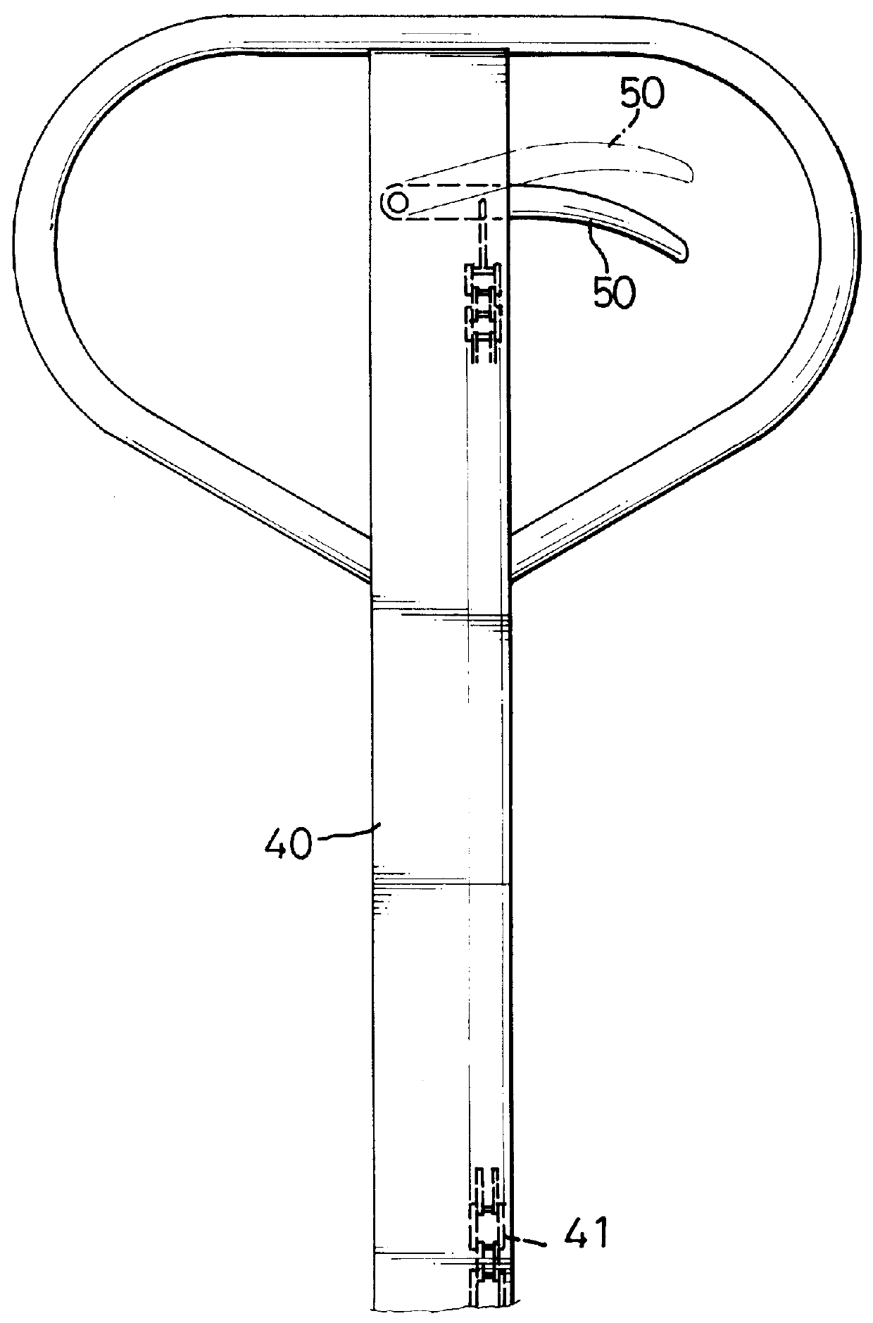
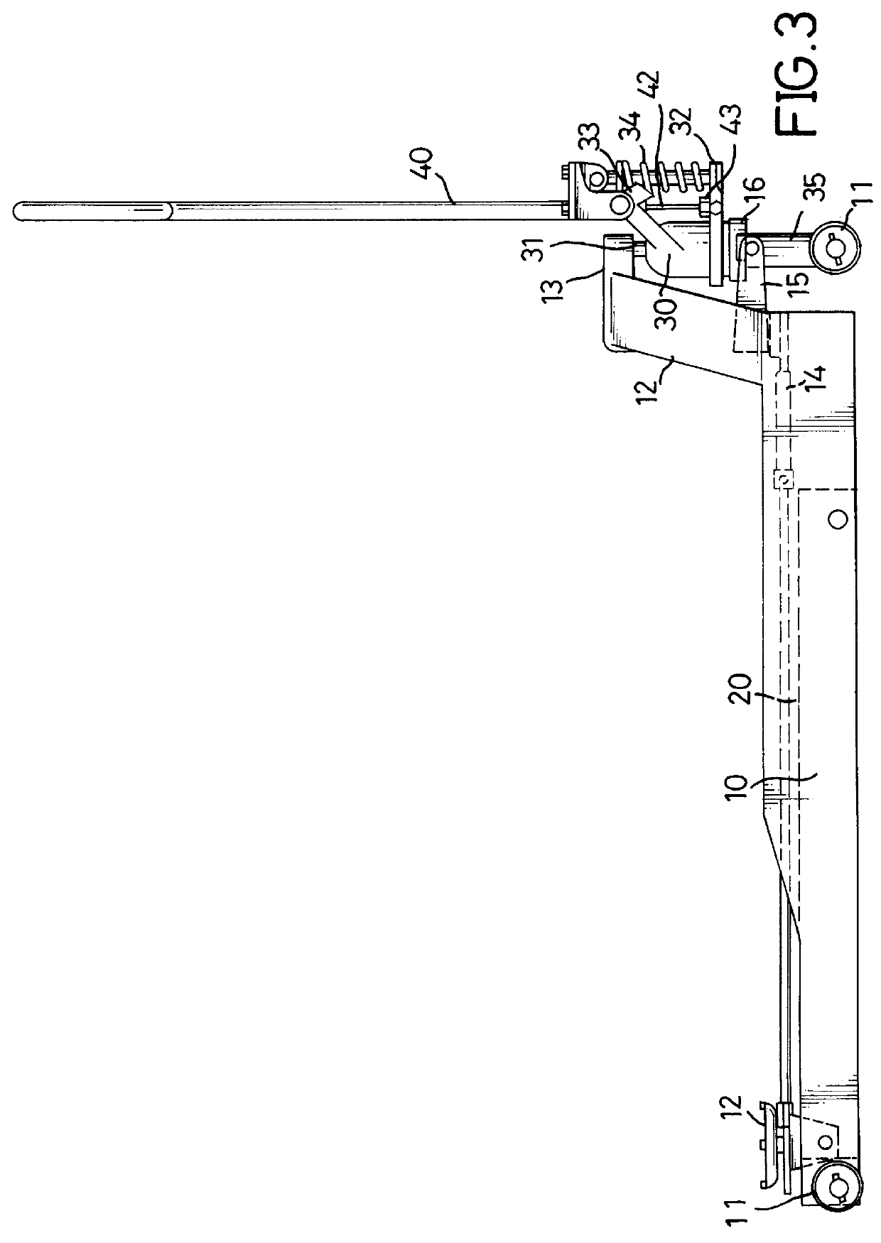
Referring to FIG. 1, it is noted that a hydraulic jack constructed in accordance with the invention has a substantially U-shaped base (10) with a plurality of wheels (11) rotatably mounted under the base (10), an elevator (20) pivotally mounted in relation with the base (10), a hydraulic cylinder (30) mounted at a first end of the base (10), a handle (40) pivotally mounted at the first end of the base (10) and a quick-release handle (50) pivotally mounted beside the handle (40).

The base (10), beside the wheels (11), has a bracket (12) securely mounted (preferably formed therewith) at one end thereof, an extension (13) integrally formed on top of the bracket (12), a plate (14) securely mounted across the base (10), two protrusions (15) respectively and extending in parallel from one side of the plate (14) and a bearing (16) securely mounted between the two protrusions (15).

The elevator (20) has a seat (21) mounted thereon and at the second end of the base (10). The hydraulic cylinder...


PUM


Abstract

A hydraulic jack is disclosed. The hydraulic jack has a bearing (16) provided under the hydraulic cylinder (30), such that the handle (40) is able to steer the hydraulic jack to any direction as required. A quick-release handle (50) connected with a control plate (43) communicating with the hydraulic cylinder (30) is provided beside the handle (40) so as to facilitate the release of the pressure built up in the hydraulic cylinder (30).

Description

1. Field of the InventionThe present invention relates to a hydraulic jack, and particularly to a hydraulic jack having a quick-release handle for releasing the hydraulic pressure in the cylinder and a pair of steering wheels rotatably mounted thereunder for moving the hydraulic jack sidewardly easily.2. Description of Related ArtThe main purpose of a jack is to elevate object upward so that users are able to work on the underside of the object. A conventional hydraulic jack is shown in FIG. 6. The hydraulic jack comprises a substantially U-shaped base (60) with a plurality of wheels (601) mounted thereunder, a hydraulic cylinder (61) securely received in the base (60), a handle (62) operatably and pivotally connected with the hydraulic cylinder (61), a release button (63) mounted beside the hydraulic cylinder (61) and in communication with the hydraulic cylinder (61), a piston rod (64) extendably connected with the hydraulic cylinder (61) and an elevator (65) pivotally connected wi...

Claims


Application Information

Patent Timeline
Patent Type & Authority Patents(United States)
IPC IPC(8): B66F5/00B66F5/04
CPCB66F5/04
Inventor LEE, STEVEN
Owner LEE STEVEN
Why Eureka
Try Eureka