FET-bipolar electronic ballast

a bipolar electronic ballast and fet technology, applied in the field of ballasts, can solve problems such as possible damage to the inverter

Inactive Publication Date: 2000-08-22
NILSSEN OLE K
View PDF6 Cites 12 Cited by
  • Summary
  • Abstract
  • Description
  • Claims
  • Application Information

AI Technical Summary

Benefits of technology

e) control means connected in circuit with the half-bridge inverter and its L-C output circuit, the control means being operative to control the symmetry of the inverter's squarewave output voltage: i) as a function of the magnitude of the voltage developing across the capacitor of the L-C circuit and in such manner that the magnitude of the voltage developing across this capacitor will never exceed a pre-determined safe magnitude, therefore automatically preventing the L-C circuit from ever drawing an excessive amount of power from the inverter, and ii) as a function of an alternative control input.

Problems solved by technology

In inverter-type fluorescent lamp ballasts using a series-excited parallel-loaded resonant L-C circuit for matching the inverter's output to the fluorescent lamp, an important problem relates to possible damage of the inverter in case the series-excited parallel-loaded resonant L-C circuit is left unloaded, such as may occur if the fluorescent lamp were to be removed.

Method used


Image

  • FET-bipolar electronic ballast
  • FET-bipolar electronic ballast
  • FET-bipolar electronic ballast

Examples


Embodiment Construction

Details of Construction

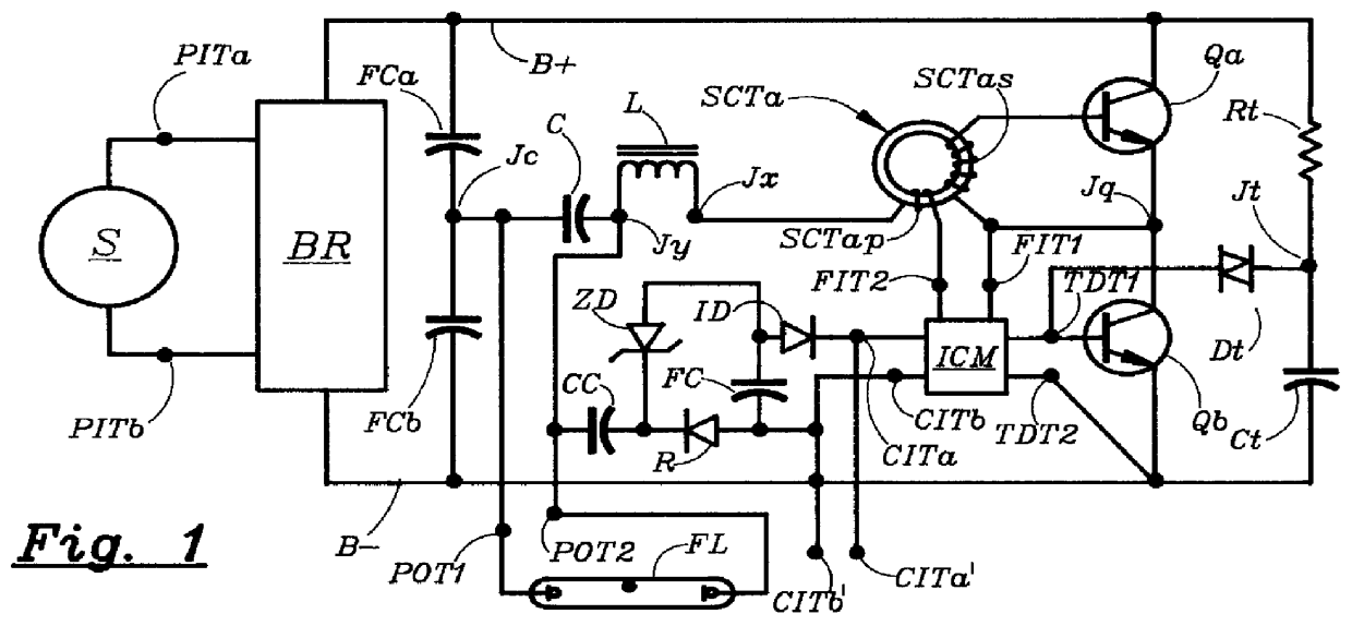
FIG. 1 schematically illustrates the electrical circuit arrangement of the initial embodiment.

In FIG. 1, a source S of ordinary 120 Volt / 60 Hz power line voltage is applied to power input terminals PITa and PITb; which terminals, in turn, are connected with a bridge rectifier BR. The DC output from bridge rectifier BR is applied to a B+ bus and a B- bus, with the B+ bus being of positive polarity.

A first filter capacitor FCa is connected between the B+bus and a junction Jc; and a second filter capacitor FCb is connected between junction Jc and the B- bus.

A first switching transistor Qa is connected with its collector to the B+ bus and with its emitter to a junction Jq.

A second switching transistor Qb is connected with its collector to junction Jq and with its emitter to the B- bus.

An inverter control means ICM has a pair of feedback input terminals FIT1 and FIT2, a pair of transistor drive terminals TDT1 and TDT2, and a pair of control input terminals CITa and...


PUM


Abstract

In a power-line-operated high-frequency electronic ballast, a half-bridge inverter is powered from a DC supply voltage and a fluorescent lamp is connected with the inverter's more-or-less asymmetrical squarewave output voltage by way of a of a series-resonant L-C circuit. The amount of power supplied by the inverter to the series-resonant L-C circuit and/or to the fluorescent lamp at any given moment depends on four significant factors: (i) the instantaneous magnitude of the DC supply voltage, (ii) the instantaneous frequency of the inverter's squarewave output voltage, (iii) the symmetry of the inverter's squarewave output voltage (which determines the effective magnitude of of its fundamental frequency voltage component), and (iv) the instantaneous operational characteristics of the fluorescent lamp. Arrangements are provided whereby the symmetry, and thereby the effective magnitude, of the inverter's output voltage is automatically adjusted so as to prevent inverter overload in case the fluorescent lamp is non-present or inoperative. The half-bridge inverter includes a bipolar transistor series-connected with a FET. The bipolar transistor operates with a substantially constant per-cycle ON-time, whereas the FET operates with a per-cycle ON-time of controllable duration.

Description

1. Field of InventionThe present invention relates to ballasts with inverters having series-tuned L-C output circuitry by which to provide a magnitude-controllable sinusoidal output voltage to a lamp load.2. Elements of Prior ArtIn inverter-type fluorescent lamp ballasts using a series-excited parallel-loaded resonant L-C circuit for matching the inverter's output to the fluorescent lamp, an important problem relates to possible damage of the inverter in case the series-excited parallel-loaded resonant L-C circuit is left unloaded, such as may occur if the fluorescent lamp were to be removed. To prevent such damage from occurring, it is necessary to provide means whereby the maximum power drawn from the inverter be manifestly limited to a safe level.For instance, such limitation is accomplished by Zansky in U.S. Pat. No. 4,392,087 by using the inverter's DC supply as an alternative load which, by way of rectifier means, activates as soon as the output voltage exceeds a certain magni...

Claims


Application Information

Patent Timeline
Patent Type & Authority Patents(United States)
IPC IPC(8): H05B41/28H05B41/282H05B41/285H05B41/39H05B41/392
CPCH05B41/2827H05B41/2828H05B41/2855H05B41/3927Y10S315/07Y10S315/05Y10S315/04
Inventor NILSSEN, OLE K.
Owner NILSSEN OLE K
Why Eureka
Try Eureka