Power supply management system

a management system and power supply technology, applied in the direction of computer control, process and machine control, instruments, etc., can solve the problems of excessive power consumption, high power consumption, and use of high power consumption time slots, so as to prevent the total amount of excess solar power, the power generation capacity of solar power generation devices can be effectively utilized, and the effect of inexpensive electrical energy

Active Publication Date: 2020-02-11
TOYOTA JIDOSHA KK
View PDF22 Cites 0 Cited by
  • Summary
  • Abstract
  • Description
  • Claims
  • Application Information

AI Technical Summary

Benefits of technology

[0006]In a residence of the consumer, there are household electrical loads with relatively low power consumption, such as household appliances (a television, a microwave oven, an air conditioner, lights, and the like). Further, in the residence of the consumer, there is often a load (hereinafter also referred to as “high power consumption load”) with extremely high power consumption as compared to the household electrical loads, for example, a charge / discharge device configured to charge a vehicle-mounted storage battery of a plug-in hybrid vehicle or electric vehicle, etc. (hereinafter referred to as “PHV / EV etc.”). Therefore, when the consumer charges the vehicle-mounted storage battery, for example, in the time slot with the low electricity fee, a large amount of power consumption may be shifted from a time slot with the large amount of power consumption to a time slot with the small amount of power consumption, and hence the amount of power consumption may be leveled more reliably.

Problems solved by technology

Further, in the residence of the consumer, there is often a load (hereinafter also referred to as “high power consumption load”) with extremely high power consumption as compared to the household electrical loads, for example, a charge / discharge device configured to charge a vehicle-mounted storage battery of a plug-in hybrid vehicle or electric vehicle, etc.
However, it is often the case that a time slot in which the consumer uses the high power consumption load, for example, the PHV / EV etc.
In other words, the time slot in which the high power consumption load is used (for example, the time slot in which the vehicle-mounted storage battery is charged in the residence of the consumer) is often restricted.
As a result, there is a problem that it is not easy to more appropriately level the amount of power consumption.

Method used


Image

  • Power supply management system
  • Power supply management system
  • Power supply management system

Examples


Embodiment Construction

[0046](Configuration of System)

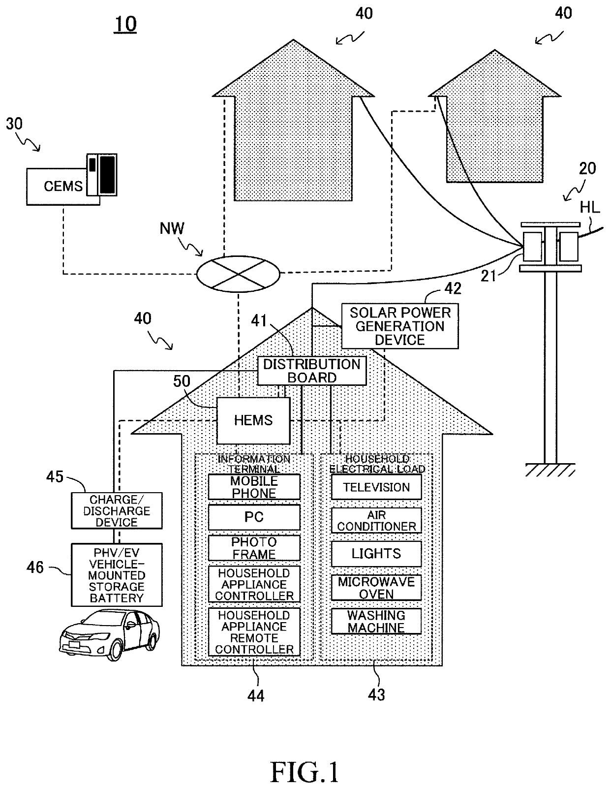
[0047]In FIG. 1, a schematic configuration of a power supply management system (hereinafter also referred to as “this system”) 10 according to an embodiment of the present invention is illustrated. This system 10 also serves as a power fee-related information provision system configured to notify a consumer of information on a power fee unit price. This system 10 includes a commercial power supply system 20, a community energy management system (CEMS) 30, and residences 40 of a plurality of consumers (individual users of electric power). In FIG. 1, the solid line indicates an electric power line, and the broken line indicates a data communication line.

[0048]The commercial power supply / source system (power supply system) 20 is a system configured to transmit electric power generated in a power plant (for example, thermal power plant) of an electric power supplier (electric power company) to “the residences 40 and unillustrated user facilities, such as a...


PUM


Abstract

A power supply management system according to an embodiment of the present invention includes a fee setting unit configured to set power fee unit prices (first power fee unit price and second power fee unit price) for each time slot, and a notification unit configured to notify a consumer of information on the set power fee unit prices. The first power fee unit price is a power unit price for a household electrical load, and the second power fee unit price is a power unit price in a case of using a charge / discharge device to charge a vehicle-mounted storage battery. The fee setting unit is configured to set, by predicting a load factor of a transformer, a discount rate of the second power fee unit price to become higher (second power fee unit price to become lower) as the predicted load factor becomes lower. The second power fee unit price is determined on the basis of the first power fee unit price and the discount rate.

Description

CROSS-REFERENCE TO RELATED APPLICATIONS[0001]This is a national phase application based on the PCT International Patent Application No. PCT / JP2015 / 078524 filed Oct. 7, 2015, claiming priority to Japanese Patent Application No. 2014-216533 filed Oct. 23, 2014, the entire contents of both of which are incorporated herein by reference.TECHNICAL FIELD[0002]The present invention relates to a power supply management system, which is capable of providing information on at least an electricity fee to a consumer of electric power.BACKGROUND ART[0003]There has been known, as the related art, an apparatus configured to receive information on an electricity fee (power fee unit price) for each time slot from the outside, and to notify a consumer (user) of the received information on the electricity fee for each time slot (see, for example, Patent Literature 1).[0004]In general, in order to level a proportion of an amount of power consumption (amount of demand power) to an amount of generated pow...

Claims


Application Information

Patent Timeline
Patent Type & Authority Patents(United States)
IPC IPC(8): G06Q50/06H02J7/35H02J3/00H02J3/38H02J3/14G06Q30/04G05B15/02
CPCH02J3/14G06Q50/06G06Q30/04H02J3/38H02J7/35G05B15/02H02J3/003H02J2310/14Y02B70/3225Y04S20/222Y04S50/12B60L53/00H02J2300/24H02J3/381B60L53/51Y02B10/10Y02E10/56Y02T10/70Y02T90/12Y02T10/7072Y04S20/242Y02B70/30H02J2310/64
Inventor HIRATA, TETSUYAKAWAMOTO, MASAYUKIKOREISHI, JUNMORII, TATSUYAITO, KOSHIMATSUNAGA, KENGOYAMADA, TAKAHIRO
Owner TOYOTA JIDOSHA KK
Why Eureka
Try Eureka