Cardiac lead with ETEE coated DBS coil

a technology of etee and coil, which is applied in the direction of conductor screwing into other, electrotherapy, therapy, etc., can solve the problems of more problematic passage of distal end 86 through the crimp assembly 30 and difficulty for physicians

Inactive Publication Date: 2000-10-31
INTERMEDICS
View PDF10 Cites 95 Cited by
  • Summary
  • Abstract
  • Description
  • Claims
  • Application Information

AI Technical Summary

Problems solved by technology

The tight bend of the distal end 86 combined with the internal structure of the lead 10 can create difficulties for the physician at the time of implantation.
However, the passage of the distal end 86 through the crimp assembly 30 is more problematic.

Method used


Image

  • Cardiac lead with ETEE coated DBS coil
  • Cardiac lead with ETEE coated DBS coil
  • Cardiac lead with ETEE coated DBS coil

Examples


embodiment

Preferred Embodiment

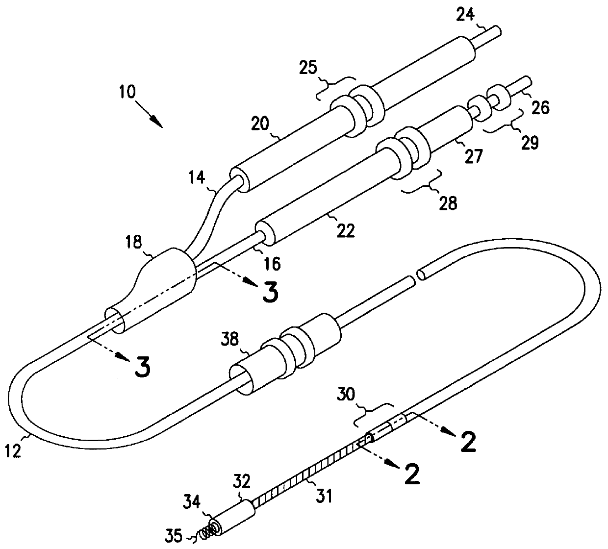
An exemplary embodiment of a cardiac stimulator lead 90 in accordance with the present invention may be understood by referring now to FIGS. 6, 7 and 8. This invention eliminates the need for crimp sleeves, described above, thereby improving the flexibility of the lead and the ease of inserting a stylet. FIGS. 7 and 8 are sectional views of FIG. 6 taken, respectively, at sections 7--7 and 8--8. For clarity of illustration, certain components of the lead 90 are shown in full in FIG. 8. The cardiac stimulator lead 90 includes a lead body 92 that has a tubular insulating sleeve 94 which bifurcates proximally into two segments 96 and 98 at a branch assembly 100. The length of the lead body 92 is such that it is shown broken. A suture sleeve 101 is slipped over and used to secure the lead body 92 at a preselected point in the patient's body. The segment 96 terminates in a connector 102 and the segment 98 terminates in a connector 104. The connector 102 is provided wit...


PUM


Abstract

A cardiac lead is provided that includes a connector for coupling to a cardiac stimulator and a first flexible insulating sleeve coupled to the connector. A second flexible insulating sleeve is coupled to the connector and has a portion positioned inside the first flexible insulating sleeve. A first conductor wire is provided that has at least a first loop and a second loop. The first and second loops are positioned between the portion of the second flexible insulating sleeve and the first insulating sleeve. A second conductor wire is provided that has a third loop. The third loop is positioned between the portion of the second flexible insulating sleeve and the first insulating sleeve. The first and second conductor wires are spiraled together so that the third loop is positioned between the first and second loops. The lead provides for the union of two conductors in a flexible structure that facilitates passage of a highly curved stylet.

Description

1. Field of the InventionThis invention relates generally to cardiac stimulator leads, and more particularly to a cardiac stimulator lead having an improved structure for joining the ends of two conductor wires.2. Description of the Related ArtConventional cardiac stimulator systems consist of a cardiac stimulator and an elongated flexible cardiac lead that is connected proximally to a header structure on the cardiac stimulator and is implanted distally at one or more sites within the heart requiring cardiac stimulation or sensing. The cardiac stimulator is normally a pacemaker, a cardioverter / defibrillator, a sensing instrument, or some combination of these devices. At the time of implantation, the distal end of a cardiac lead is inserted through an incision in the chest and manipulated by the physician to the site requiring electrical stimulation with the aid of a flexible stylet that is removed prior to closure. At the site requiring electrical stimulation, the distal end of the ...

Claims


Application Information

Patent Timeline
Patent Type & Authority Patents(United States)
IPC IPC(8): A61N1/05H01R4/00H01R4/56
CPCA61N1/056H01R4/56H01R2201/12
Inventor PATAG, ALFREDO E.
Owner INTERMEDICS
Why Eureka
Try Eureka