Rotary drill bit having moveable formation-engaging members

a technology of formation-engaging members and drill bits, which is applied in the direction of drilling machines and methods, cutting machines, constructions, etc., can solve the problems of drill bits being subject to instability and vibration, cutting elements to crack or fracture, and impact loads may occur

Inactive Publication Date: 2000-11-07
REEDHYCALOG UK
View PDF25 Cites 200 Cited by
  • Summary
  • Abstract
  • Description
  • Claims
  • Application Information

AI Technical Summary

Problems solved by technology

During drilling operations, the cutting structures of such a bit may be subject to impact loads which may cause the cutting elements to crack or fracture.
Also, such impact loads may occur when the drill passes through a comparatively soft formation and strikes a significantly harder formation, or when the drill bit encounters hard occlusions within a generally soft formation.
In addition, such drill bits may be subject to instability and vibration.
Bit whirl may lead to t

Method used


Image

  • Rotary drill bit having moveable formation-engaging members
  • Rotary drill bit having moveable formation-engaging members
  • Rotary drill bit having moveable formation-engaging members

Examples


Embodiment Construction

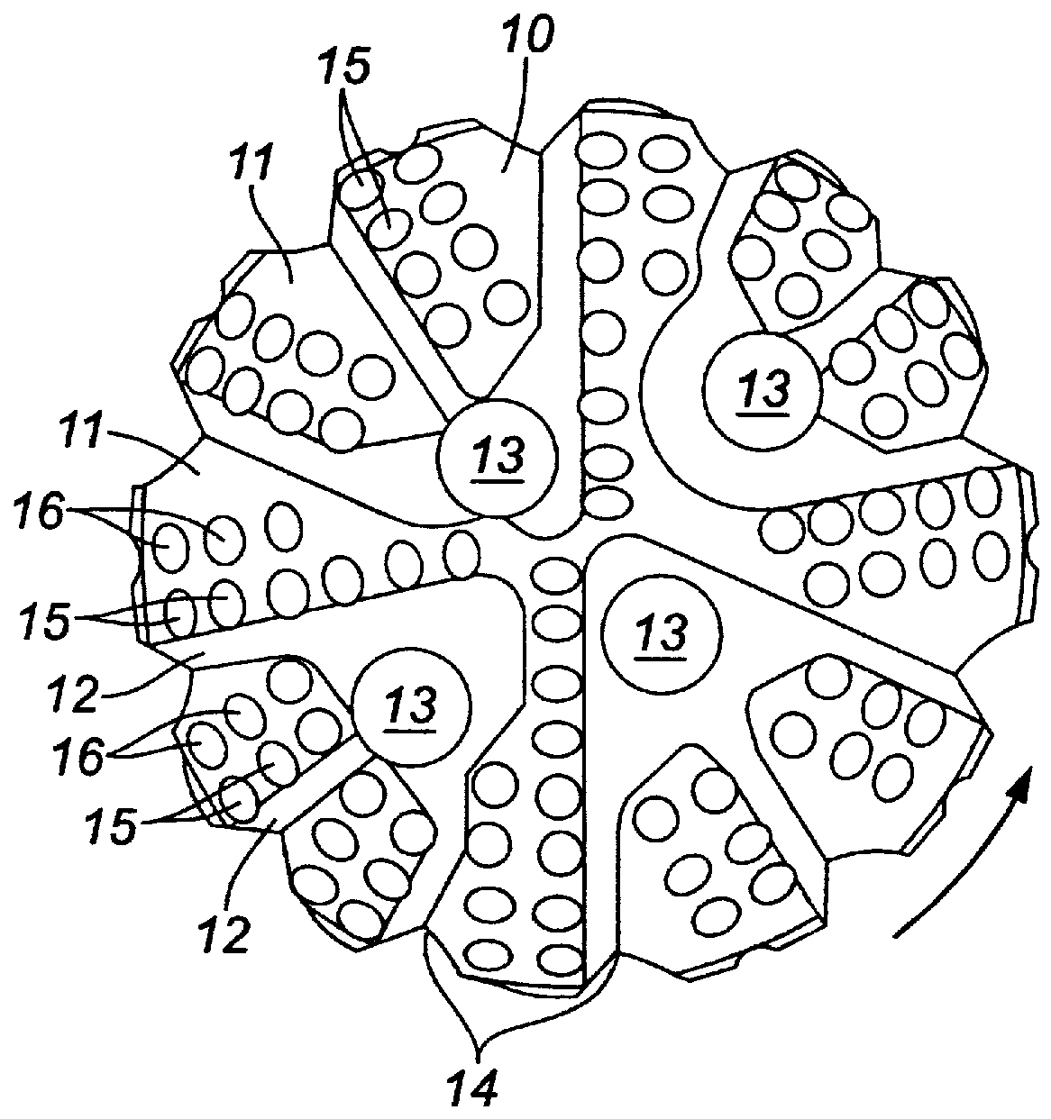
The rotary drill bit shown diagrammatically in FIG. 1 is of the kind commonly referred to as a PDC (polycrystalline diamond compact) drag-type drill bit. The bit body has a leading end face 10 formed with a number of blades 11. The blades 11 extend from the surface of the bit body to define a plurality of channels 12 between the blades 11. The nozzles 13 are positioned within the channels 12. The nozzles 13 receive drilling fluid from passages (not shown) within the bit body, and the nozzles 13 deliver this drilling fluid to the channels 12. Drilling fluid flowing outwardly along the channels 12 cleans the blades 11 and passes to junk slots 14 in the gauge portion of the bit. The drilling fluid then flows back to the surface through the annulus between the drill string and the surrounding wall of the borehole.

Mounted on each blade 11 is a row of cutting structures 15 (shown diagrammatically). The cutting structures 15 face into the adjacent channels 12 so as to be cooled and cleaned...


PUM


Abstract

Formation engaging elements are moveably mounted onto a drill bit. Such elements may be used to protect other rigidly mounted formation engaging elements from impacts that occur during use of the drill bit, or they may be used to alter the aggressiveness of the drill bit when used in directional drilling operations.

Description

1. Field of the InventionThe invention relates to rotary drill bits for use in drilling holes in subsurface formations and, more particularly, to rotary drill bits having moveable formation-engaging members.2. Background of the Related ArtDrill bits for use in drilling holes in subterranean formations include cutting structures that are positioned at selected locations on a bit body. Typically, each cutting structure includes a thin facing table of superhard material, such as polycrystalline diamond, that is bonded to a substrate of a softer material, such as tungsten carbide. The general construction of bits of this kind is well known and will not be described in detail.During drilling operations, the cutting structures of such a bit may be subject to impact loads which may cause the cutting elements to crack or fracture. Such impact loads may be generated, for example, when tripping the drill bit into or out of the borehole, or when raising or lowering the drill bit temporarily at...

Claims


Application Information

Patent Timeline
IPC IPC(8): E21B7/04E21B7/06E21B44/00E21B10/00E21B10/46E21B10/62E21B10/26E21B10/56E21B10/32E21B10/54E21B10/567
CPCE21B7/068E21B10/322E21B10/325E21B44/005E21B10/54E21B10/567E21B10/62E21B10/327
Inventor GRIFFIN, NIGEL DENNISFULLER, JOHN MICHAELNEWTON, ALEXTAYLOR, MALCOLM ROYMURDOCK, ANDREWTAYLOR, STEVEN
Owner REEDHYCALOG UK
Why Eureka
Try Eureka