External cavity semiconductor laser light source

a laser light source and semiconductor technology, applied in semiconductor lasers, laser details, laser optical resonator construction, etc., can solve the problems of optical pll operation, optical pll operation cannot be carried out, optical frequency is largely drifted,

Inactive Publication Date: 2000-11-07
YOKOGAWA ELECTRIC CORP
View PDF3 Cites 9 Cited by
  • Summary
  • Abstract
  • Description
  • Claims
  • Application Information

AI Technical Summary

Problems solved by technology

However, in the case of the external cavity LD light source, the optical frequency is largely drifted because a change with the passage of time is caused, in particular, by a fluctuation in temperature.
However, after the time t.sub.2 when the DC component of the output from the first low pass filter 8 exceeded V.sub.max, the operation of the optical PLL cannot be carried out, and the drift of the optical frequency occurs with a free run state.
As a re

Method used


Image

  • External cavity semiconductor laser light source
  • External cavity semiconductor laser light source
  • External cavity semiconductor laser light source

Examples


first embodiment

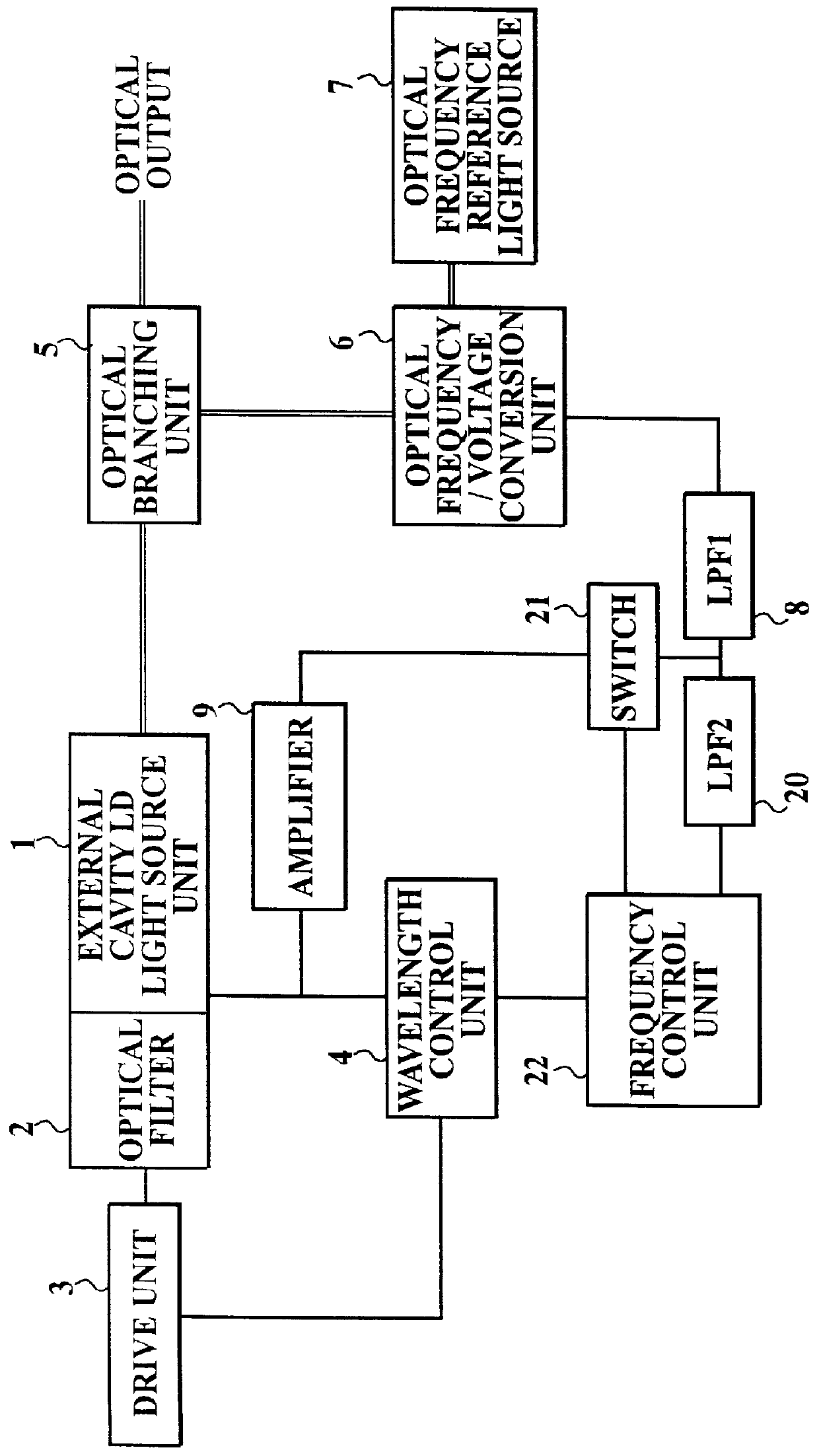
FIG. 1 is a block diagram showing a construction of an optical frequency stabilized external resonator of LD light source according to first embodiment to which the present invention is applied. In this figure, the same elements and the like as corresponding to ones shown in FIG. 5 have the same reference numerals, and the detailed explanation for them will be omitted.

In FIG. 1, the reference numeral 20 denotes a second low pass filter (LPF2), 21 denotes a switch, and 22 denotes a frequency control unit.

That is, in this embodiment, as shown in FIG. 1, the second low pass filter 20 is provided between the first low pass filter 8 and the frequency control unit 22 connected with the wavelength control unit 4 so as to be in parallel with the amplifier 9. The switch 21 is provided between the amplifier 9 and the first low pass filter 8, and is also connected with the frequency control unit 22 to receive an on or off control signal therefrom.

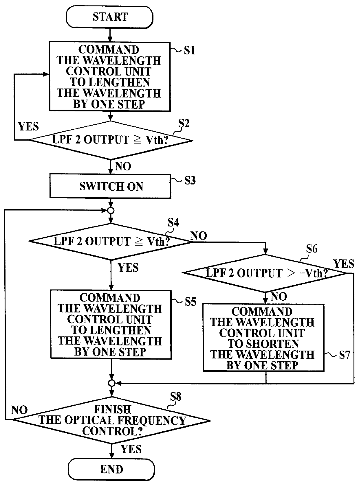
The frequency control unit 22 for checking the ...

second embodiment

FIG. 4 is a block diagram showing a construction of an optical frequency stabilized external resonator of LD light source according to second embodiment to which the present invention is applied. In this figure, the same elements and the like as corresponding to ones shown in FIG. 1 have the same reference numerals, and the detailed explanation for them will be omitted.

In FIG. 4, the reference numeral 23 denotes a second drive unit (drive unit 2).

That is, in this embodiment, as shown in FIG. 4, the second drive unit 23 is provided in addition to the construction of an optical frequency stabilized external resonator of LD light source according to first embodiment. The second drive unit 23 is controlled by the frequency control unit 22.

In this embodiment, the optical frequency stabilized external cavity LD light source shown in FIG. 4 can be operated basically the same as that shown in FIG. 1.

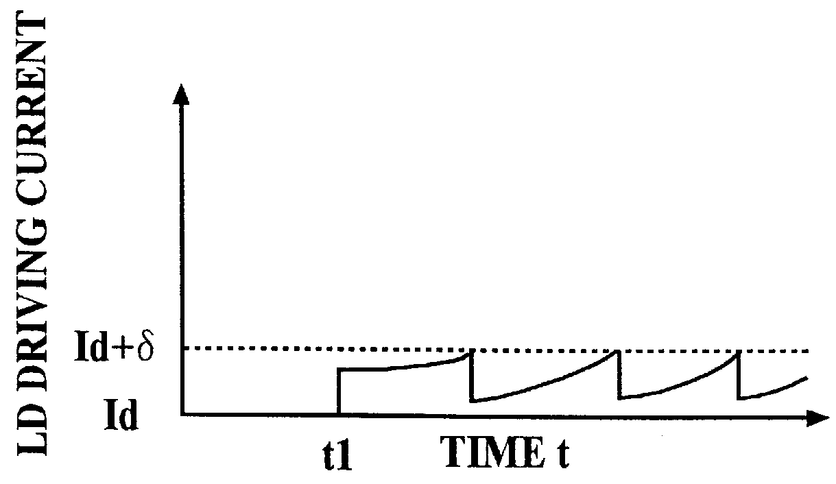
In the case that the continuous wavelength tuning can be carried out by the first drive unit...


PUM


Abstract

An external cavity semiconductor laser light source which comprises: an external cavity semiconductor laser light source unit; an optical filter for selecting an output beam of the external cavity semiconductor laser light source unit in a single mode; a drive unit for varying a wavelength of a transmitted light or a wavelength of a reflected light, from the optical filter; a wavelength control unit for controlling the drive unit; an optical frequency reference light source for generating a light having a reference optical frequency; an optical frequency/voltage conversion unit for generating a signal which corresponds to a difference in optical frequency between the light outputted from the optical frequency reference light source and the output beam of the external cavity semiconductor laser light source unit; a low pass filter for transmitting a low-frequency component of the signal of the optical frequency/voltage conversion unit; a switch for feeding the signal into the external cavity semiconductor light source and for interrupting the signal; and a frequency control unit for switching on and off the switch to control the drive unit.

Description

1. Field of the InventionThe present invention relates to an external cavity semiconductor laser light source which is used in any technical field which requires a light signal source, in particular, which is used in an optical telecommunication or a coherent optical measuring technical field.2. Description of the Related ArtIn the coherent optical measuring technical field, an external cavity semiconductor laser (hereinafter, may be simply referred to LD) is generally used as a light source unit in a light source tunable in wavelength. An optical filter which is a wavelength selection element is disposed in the external resonator thereof to get a single mode oscillation.Such a technique enables wavelength scanning in a wide range by mechanically varying the transmitted (or reflected) wavelength from the optical filter.In an optical frequency stabilized member, an optical PLL (phase-looked loop) for feeding back an electric current into an LD driving current, which is proportional t...

Claims


Application Information

Patent Timeline
IPC IPC(8): H01S5/14H01S5/00H01S5/0687
CPCH01S5/141H01S5/0687
Inventor HAMADA, MADOKA
Owner YOKOGAWA ELECTRIC CORP
Why Eureka
Try Eureka