

Circuit and method for converting interrupt signals from level trigger mode to edge trigger mode
a technology of interrupt signals and trigger modes, applied in the field of interrupt signals, can solve the problems of wasting the execution time of an extraneous interrupt cycle by the cpu
Inactive Publication Date: 2000-11-07
VLSI TECHNOLOGY
View PDF5 Cites 11 Cited by
- Summary
- Abstract
- Description
- Claims
- Application Information
AI Technical Summary
Problems solved by technology
The CPU thus wasted the execution time of an extraneous interrupt cycle.
This problem was caused by using the end of the interrupt acknowledge cycle as the end of the interrupt cycle, since the original level trigger mode interrupt request signal could still be active at this time and could be interpreted by the CPU as a second interrupt.
Method used
View moreImage
Smart ImageViewing Examples

Examples
second embodiment
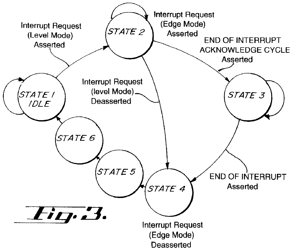
interrupt converter 10 in accordance with the present invention is shown by the state diagram of FIG. 3. In this implementation, State 5 and State 6 are added to provide additional time delay between State 4 and State 1.
third embodiment
interrupt converter 10 in accordance with the present invention is shown by the state diagram of FIG. 4. In this third embodiment, State 1 and State 4 of FIG. 2 are combined into a new State 1, thereby minimizing the number of states needed to implement interrupt converter 10 in accordance with the present invention.
FIG. 4 shows a typical implementation of the interrupt converter 10 of the present invention within a computer system.
Login to View More PUM
 Abstract
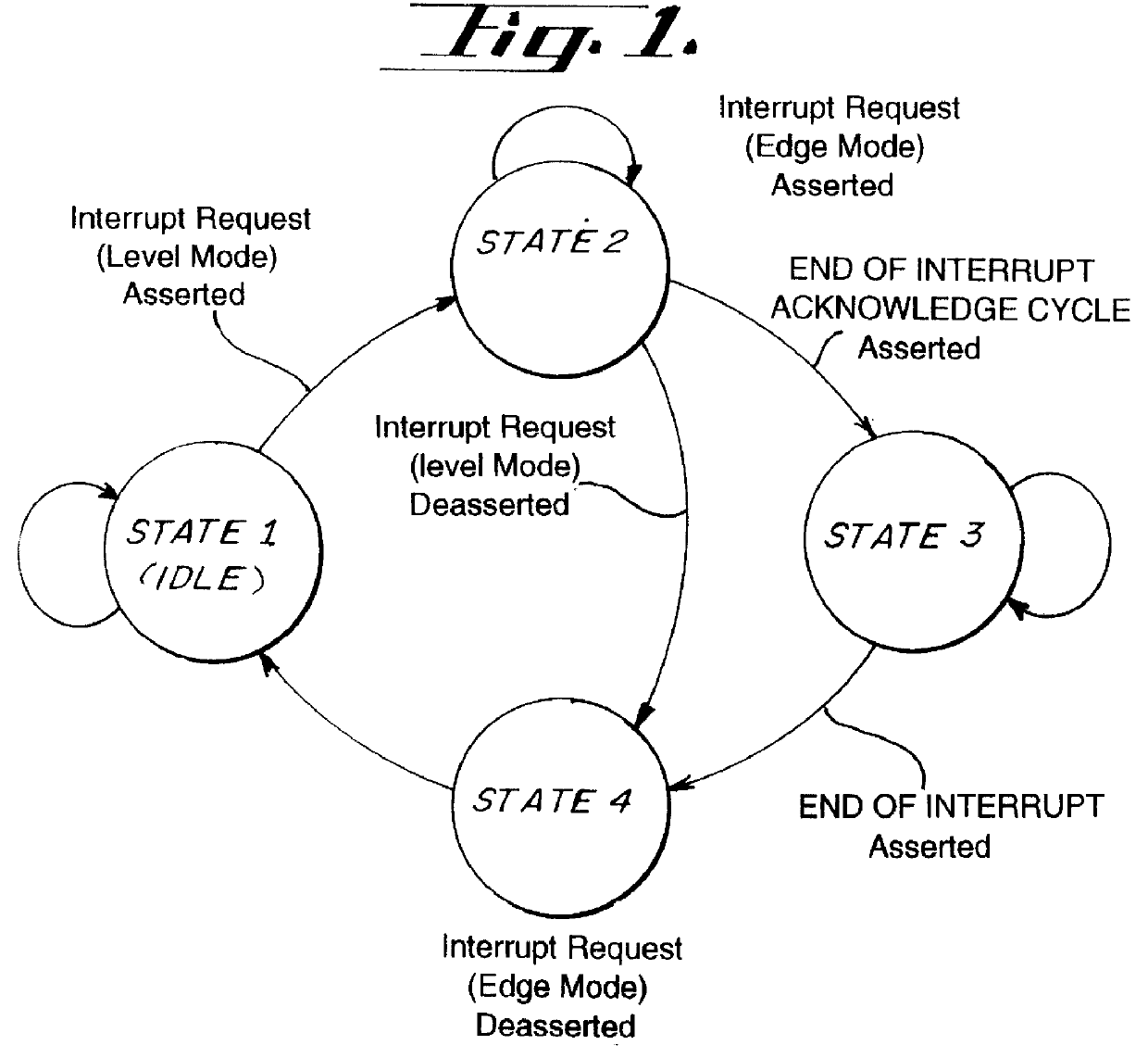
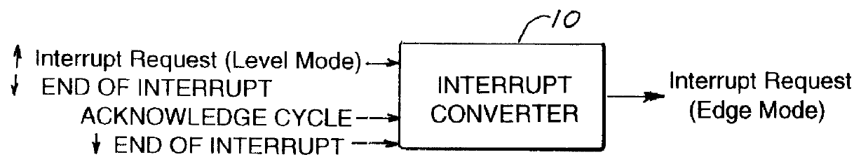
Level trigger mode interrupts are converted to edge trigger mode interrupts in a computer system. A circuit detects the occurrence of a level trigger mode interrupt request, and asserts an edge trigger mode interrupt request output. The edge trigger mode interrupt request remains asserted until an End of Interrupt input is asserted, indicating that the CPU has completed servicing the prior interrupt. The edge trigger mode interrupt request is then deasserted.
Description
1. Field of the InventionThis invention generally relates to interrupt signals in a computer system, and more specifically relates to a circuit and method for converting interrupt signals from level trigger mode to edge trigger mode.2. Description of the Related ArtIn computer systems of the prior art, interrupt request lines from peripherals to the CPU were level sensitive. The interrupt converter generally detected the end of the interrupt acknowledge cycle as the end of the interrupt cycle. After waiting the minimum inactive time needed by the interrupt request input, the CPU would be ready to detect another active interrupt request signal. However, some peripherals require interrupt service that extends beyond the occurrence of the interrupt acknowledge signal, and would still be asserting the original interrupt request signal when the CPU became ready to detect another interrupt request signal. For this reason, the CPU would generate another interrupt cycle to service the inter...
Claims
Login to View More Application Information
Patent Timeline
 Patent Type & AuthorityPatents(United States)
IPC IPC(8): G06F13/20G06F13/24
CPCG06F13/24
InventorGARINGER, NED D.YU, TEIN-YOW
OwnerVLSI TECHNOLOGY