
Respiratory failure monitoring device

A respiratory failure and monitoring device technology, applied in the evaluation of respiratory organs, instruments, alarms, etc., can solve problems such as the limitation of the use of respiratory monitoring devices and the inability to place sensors.

Inactive Publication Date: 2009-05-06
张海艇
View PDF0 Cites 8 Cited by
  • Summary
  • Abstract
  • Description
  • Claims
  • Application Information

AI Technical Summary

Problems solved by technology

[0002] At present, the existing disclosed respiratory monitors all place a sensor at the patient's nostril, and monitor the patient's respiratory condition by detecting the presence or absence of the patient's exhaled airflow or the temperature generated by the airflow. Therefore, when the patient inhales oxygen, the sensor cannot be installed because there is an oxygen suction tube at the nostril, so that the existing respiratory monitor is limited in use.

Method used


Image

  • Respiratory failure monitoring device
  • Respiratory failure monitoring device

Examples


Embodiment Construction

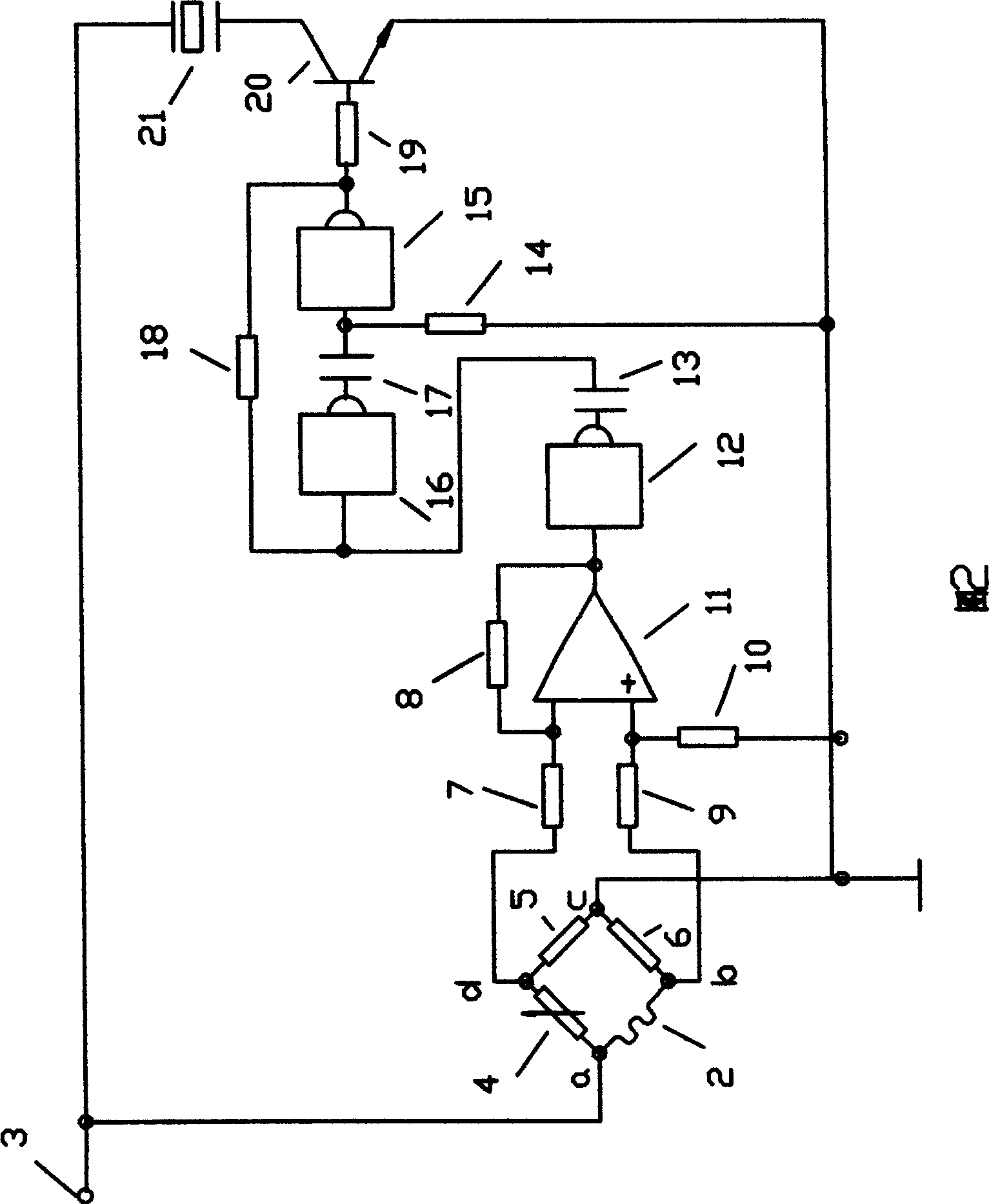
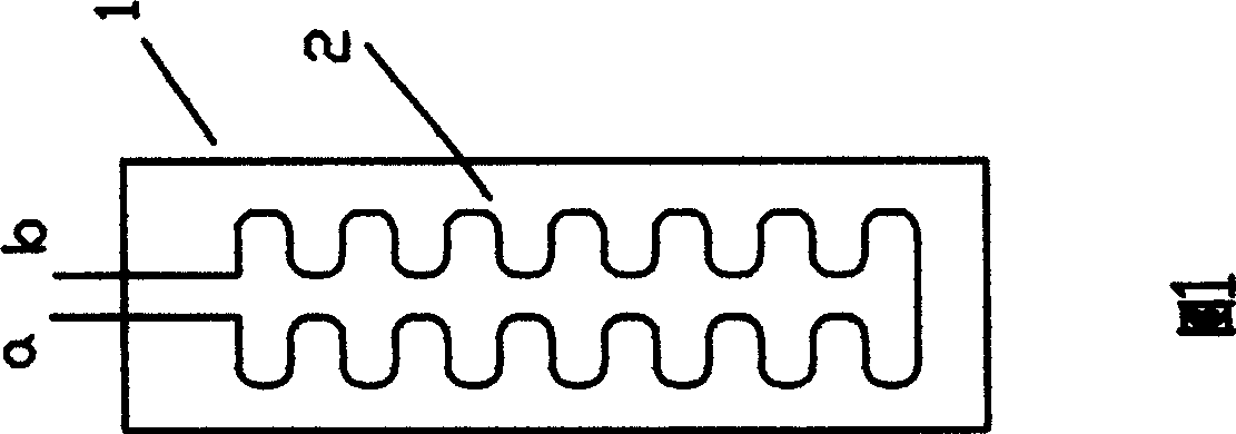
[0008] The implementation scheme of the present invention will be described in detail with reference to the accompanying drawings. In accompanying drawing 1, a resistance wire 2 is bent 27 times after leaving a section of straight line from a point, and then bends back 27 times and gets back to b point, a point Point b stretches out a side of fiber cloth 1, and resistance wire 2 is clamped in the middle of two fiber cloths 1, (one piece is not drawn), and resistance wire 2 and fiber cloth 1 are bonded into one. In accompanying drawing 2, resistance wire 2 and resistance 5, 6, variable resistance 4 are connected to form a Wheatstone bridge, and its input end a point is connected to power supply 3, another input end point c is grounded, and its output end point b passes through A resistor 9 is connected to the non-inverting input terminal of the operational amplifier 11, another output point d is connected to the inverting input terminal of the operational amplifier 11 through a ...


PUM


Abstract

The invention discloses a respiratory failure monitor which consists of a resistance wire and a control circuit. The resistance wire is bent into a certain shape and clamped between two pieces of fiber cloth to be integrated. When in monitoring, the monitor is fixed on the abdomen of a patient. When the patient breathes, change in length of the resistance wire results in the change of resistance value of the resistance wire, and after the differential amplification carried out by an operational amplifier, low level is output through that phase inversion is performed by a phase inverter. The low level triggers a time-delay circuit to output low level so as to block an audion and ensure that a buzzer does not give an alarm. At this moment, the time-delay circuit performs time delay. When no breath signal is detected within the set delay time, an output end of the time-delay circuit changes from low level to high level, the audion is conducted and the buzzer gives an alarm, i.e., that when breath signals can not be detected if the patient does not breathe or shallowly breathe, an alarm is given, but if respiratory signals are available within the set delay time, low level is always kept by the time-delay circuit, the audion is blocked and the buzzer does not give an alarm.

Description

Technical field [0001] The invention relates to a breathing monitor, in particular to a monitor for patients with respiratory failure. Background technique [0002] At present, the existing disclosed respiratory monitoring instruments all place a sensor at the patient's nostril, and monitor the patient's respiratory condition by detecting the presence or absence of the patient's exhaled airflow or the temperature generated by the airflow. When promptly needs to monitor, all will connect oxygen, therefore when the patient inhales oxygen, can not place sensor again because of the oxygen suction tube at the nostril place, makes existing respiratory monitoring instrument limited in use. Contents of the invention [0003] In order to overcome the shortcoming that the existing disclosed breathing monitor is limited in use, the purpose of the present invention is that the patient can also use it when inhaling oxygen. [0004] In order to achieve the above object, the technical s...

Claims


Application Information

Patent Timeline
Patent Type & Authority Applications(China)
IPC IPC(8): A61B5/08G08B21/00
Inventor 张海艇
Owner 张海艇
Learn More