Slip joint

a technology of sliding joints and joints, applied in the field of sliding joints, can solve the problems of large space occupation, heavy weight, and difficulty in inspection and changing, and the wires, the appurtenant collection reels, and other equipment associated with the tensioning apparatus of the risers, and the need to be inspected and changed relatively

Inactive Publication Date: 2000-11-21
AKER KVAERNER MH
View PDF16 Cites 45 Cited by
  • Summary
  • Abstract
  • Description
  • Claims
  • Application Information

AI Technical Summary

Problems solved by technology

The wires, tensioners, appurtenant collection reels and other equipment associated with the tensioning apparatus for the riser require consider

Method used


Image

  • Slip joint
  • Slip joint
  • Slip joint

Examples


Embodiment Construction

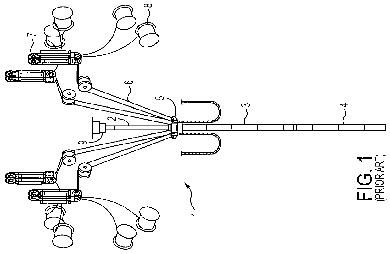
FIG. 1 shows a slide joint 1 in accordance with the prior art. Slide joint 1 consists of an inner pipe 2 and an outer pipe 3. Outer pipe 3 is connected to the rest of the riser 4, which extends down into the well (not shown). Outer pipe 3 is provided at the upper end thereof with a collar 5 to which is connected a plurality of wires 6, which in turn are connected to tensioners 7. There are also provided collection reels 8 for wire. The inner pipe is connected via a flexible coupling 9 to the production equipment on the platform (not shown). In FIG. 1 there are also shown two hoses, which are connected via ducts in riser 4 with the blow out of preventer (BOP), one of these hoses being adapted to throttle the return from the well, while the other hose is adapted for pumping kill mud down into the well.

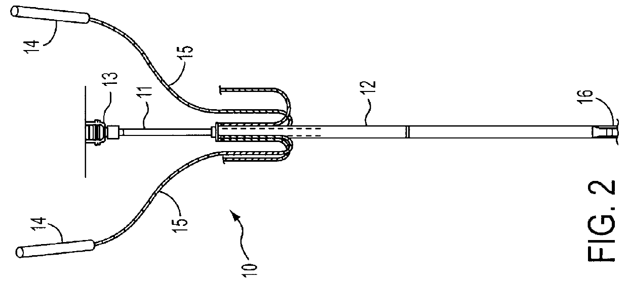
In FIG. 2 a slide joint 10 in accordance with the invention is shown. The slide joint here also consists of an inner pipe 11 and an outer pipe 12. Inner pipe 11 is here also connected to...


PUM


Abstract

PCT No. PCT/NO97/00115 Sec. 371 Date Nov. 12, 1998 Sec. 102(e) Date Nov. 12, 1998 PCT Filed May 5, 1997 PCT Pub. No. WO97/43516 PCT Pub. Date Nov. 20, 1997A slide joint for a riser between a well and a floating petroleum installation such as an oil platform includes an outer pipe and an inner pipe which are adapted to move telescopically relative to one another to compensate for changes in the distance between the sea bed and the platform. The inner pipe is connected to a piston, which piston is responsive to actuation by hydraulic pressure in order to provide tractive force on the riser. The outer diameter of the inner pipe is adapted to the diameter of the outer pipe so as to form an annulus between the pipes. The piston is fixedly connected to the inner pipe at or near the downward oriented end thereof, said annulus above the piston being subjected to hydraulic pressure. Below the piston is provided a protective sleeve, which is slidably disposed within the outer pipe.

Description

1. Field of the InventionThe present invention relates to a slide joint for a riser between a well and a floating petroleum installation, for example, an oil platform, comprising an outer pipe and an inner pipe, which pipes are adapted to move telescopically relative to one another to compensate for changes in the distance between the sea bed and the platform.2. Description of the Background InformationA known slide joint of this type is shown in FIG. 1. To maintain tension in the riser, a plurality of wires are attached to the upper end of the outer pipe, which wires in turn are connected to a plurality of tensioners, which exert a constant tension on the riser. The wires, tensioners, appurtenant collection reels and other equipment associated with the tensioning apparatus for the riser require considerable space and, in addition, are very heavy. Moreover, the wires are under substantial strain and must be inspected and changed relatively often.An object of the present invention is...

Claims


Application Information

Patent Timeline
IPC IPC(8): E21B17/02E21B17/08E21B19/00E21B19/09E21B17/01
CPCE21B19/002E21B17/085
Inventor VATNE, PER
Owner AKER KVAERNER MH
Why Eureka
Try Eureka