Pneumatic tool

a pneumatic tool and tool body technology, applied in the field of pneumatic tools, can solve the problems of large pneumatic tool size, affecting both the manufacture and operation of the tool, and complex structure of the tank (80)

Inactive Publication Date: 2000-12-19
Q C WITNESS INT
View PDF5 Cites 65 Cited by
  • Summary
  • Abstract
  • Description
  • Claims
  • Application Information

AI Technical Summary

Problems solved by technology

However, because the conventional oil tank (80) is attached to the high-pressure air connector (64) and connects with the high-pressure air hose, the structure of the tank (80) is complex and the size of t

Method used


Image

  • Pneumatic tool
  • Pneumatic tool
  • Pneumatic tool

Examples


Embodiment Construction

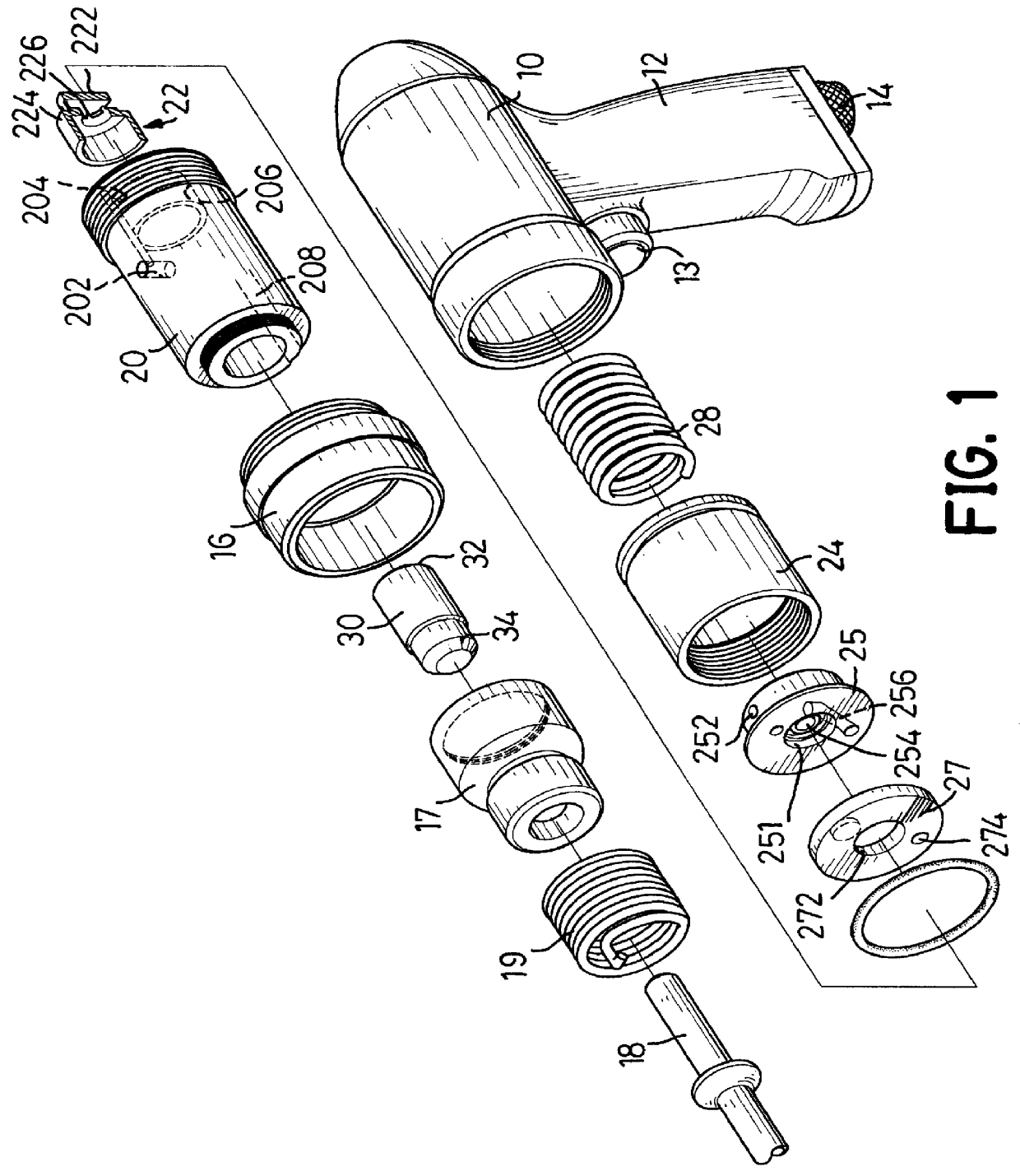
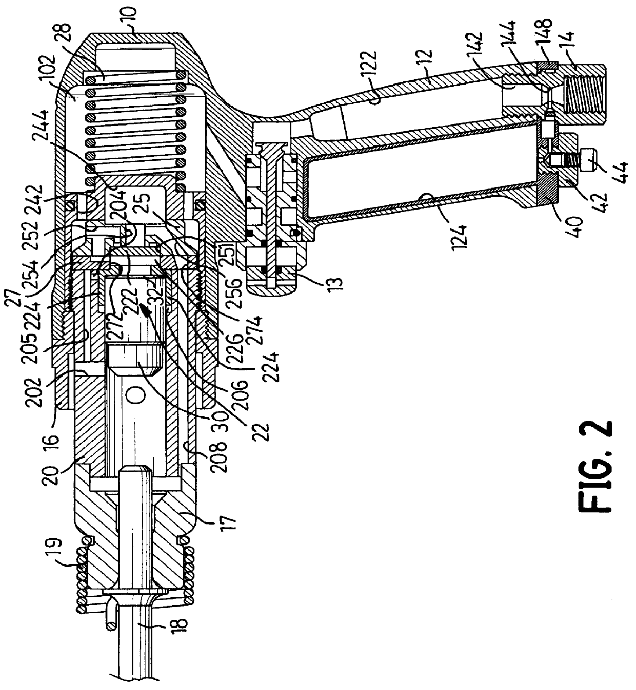
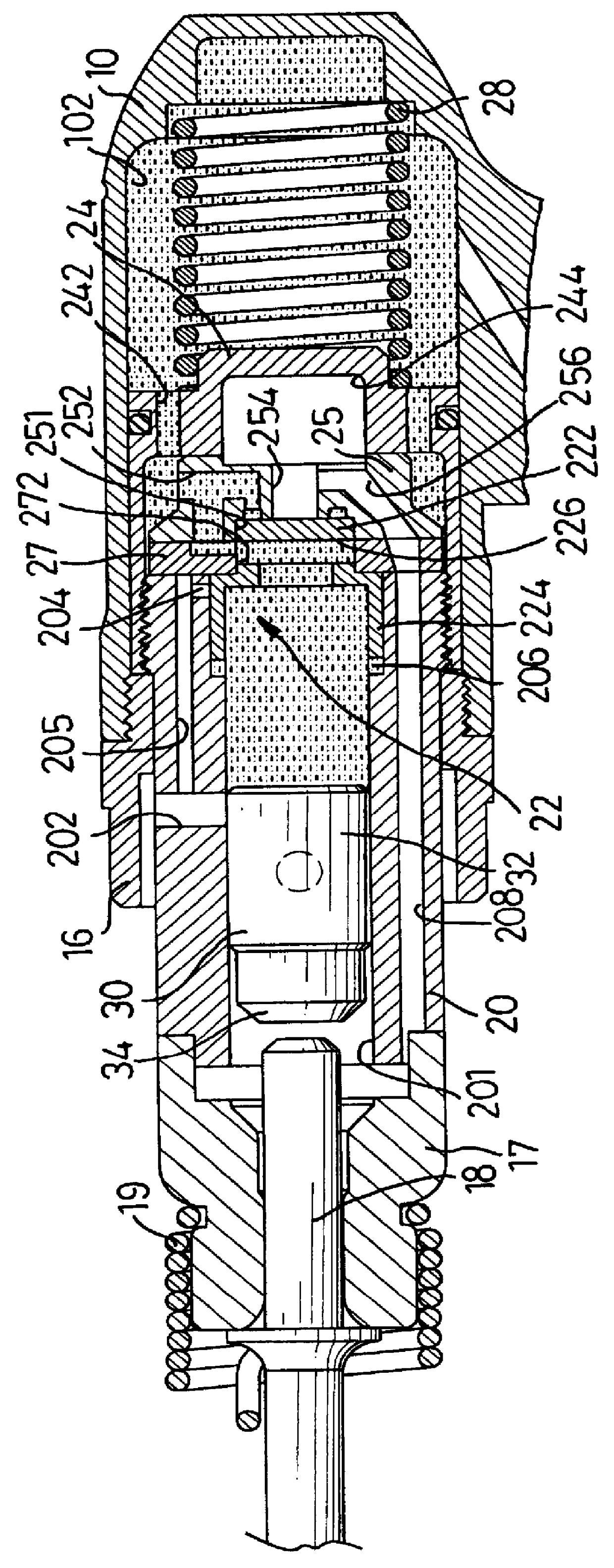
Referring to FIGS. 1 and 2, a pneumatic tool in accordance with the present invention comprises a hollow housing (10), a handle (12) integrally extending from the housing (10), an actuating mechanism mounted in the housing (10) and a tool shank (18) with a spring (19).

The housing (10) has an inner space to receive the actuating mechanism.

The handle (12) has an air passage (122) capable of communicating with the inner space of the housing (10). A high-pressure air connector (14) with a passage (142) extending therethrough is detachably mounted in the external opening of the air passage (122) to allow the high-pressure air to enter the air passage (122) and the housing (10). A trigger (13) is mounted between the housing (10) and the handle (12) to control the air stream into the housing (10).

The actuating mechanism includes a cylinder (20), a piston (30) slidably received in the cylinder (20) and a reciprocating valve mounted on one end of the cylinder (20) to control the direction of...


PUM

PropertyMeasurementUnit
Pressureaaaaaaaaaa
Diameteraaaaaaaaaa
Sizeaaaaaaaaaa

Abstract

A pneumatic tool is disclosed. The pneumatic tool has a hollow housing with a handle extending therefrom, the handle having a chamber defined therein and an air passage communicating with the housing, an actuating mechanism mounted in the housing to actuate a tool shank and a cap securely attached to said handle to cover the chamber so as to form an oil reservoir in the handle. The pneumatic tool further has a control member mounted in the actuating mechanism to control the opening and closing of a discharge passage formed in the actuating mechanism. The disclosed pneumatic tool can limit the size of the pneumatic tool and let the air completely flow out so as to improve the convenience and operational effectiveness of the pneumatic tool.

Description

1. Field of the InventionThe present invention relates to a pneumatic tool, and more particularly to a pneumatic tool with a lubricating oil reservoir.2. Description of Related ArtA pneumatic tool like a pneumatic chisel in accordance with the prior art shown in FIG. 10 comprises a hollow housing (60) with an actuating mechanism (70) and a handle (62) extending from the hollow housing (60) to connect with a high-pressure air source with a high-pressure air connector (64). The actuating mechanism (70) includes a reciprocating valve (72) to control the direction of the air flow to propel an piston (76) to slide along a cylinder (74) forwards and backwards. Consequently, the high-pressure air can be directed into the hollow housing (60) through the high-pressure air connector (64) and the handle (62), and the actuating mechanism (70) will be actuated to impact a tool shank (78) for hammering or chiseling. In addition, a lubricating oil tank (80) is mounted on the high-pressure air conn...

Claims


Application Information

Patent Timeline
IPC IPC(8): B25D9/20B25D9/00
CPCB25D9/20B25D2250/341B25D2209/005
Inventor LIU, I-YUEH
Owner Q C WITNESS INT
Why Eureka
Try Eureka