Wind turbine with mixers and ejectors

A technology of wind turbines and mixers, which is applied in the direction of wind engines, wind engines consistent with the wind direction, wind motor combinations, etc., and can solve the problems of short diffuser outflow, impracticality, and failure to work

Inactive Publication Date: 2010-03-24
FLODESIGN WIND TURBINE
View PDF5 Cites 7 Cited by
  • Summary
  • Abstract
  • Description
  • Claims
  • Application Information

AI Technical Summary

Problems solved by technology

Such long and flow-sensitive diffusers are impractical in wind turbine installations
A short diffuser would run out of flow in practical applications and would not work at all
Also, as turbine energy extraction is desired at increased speeds, the desired downstream divergence may not be achieved

Method used


Image

  • Wind turbine with mixers and ejectors
  • Wind turbine with mixers and ejectors
  • Wind turbine with mixers and ejectors

Examples


Embodiment Construction

[0048] Refer to the accompanying drawings for details, Figure 2-25 A number of alternative embodiments of Applicants' axial flow wind turbine ("MEWT") with mixer and ejector are shown.

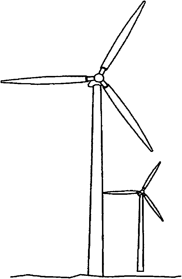
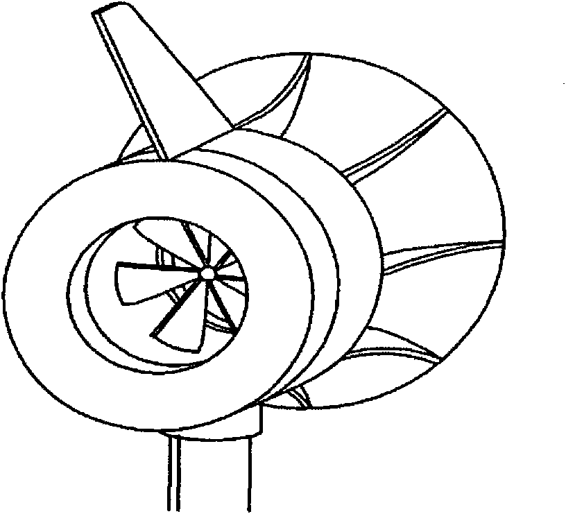
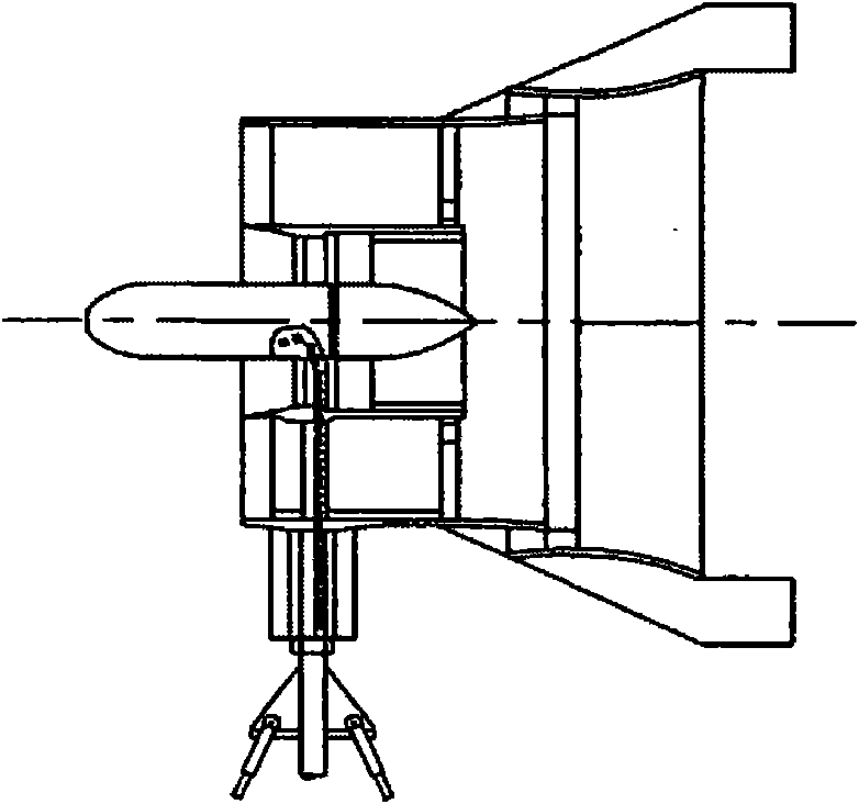
[0049] In a preferred embodiment (see figure 2 , 3 , 4, 5), MEWT 100 is an axial flow wind turbine, which includes:

[0050] (a) an aerodynamically shaped turbine shroud 102;

[0051] (b) an aerodynamically shaped central body 103 located within and connected to the turbine shroud 102;

[0052] (b) Turbine stage 104, which surrounds central body 103, and includes: stator ring 106 formed of stator blades (eg, 108a); and impeller or rotor 110, which has impeller or rotor blades (eg, 112a), said The impeller or rotor blades are located downstream and "in-line" with the stator blades (i.e., the leading edge of the impeller blade is substantially aligned with the trailing edge of the stator blade), wherein:

[0053] (i) stator blades (eg, 108a) are mounted on the central body 103;

[0054] ...


PUM


Abstract

A Mixer-Ejector Prop System (MEPS) is presented as a new, unique and improved concept for injecting power and producing force in flowing fluids such as air or water. MEPS incorporates advanced flow mixing technology, single and multi-stage ejector technology, aircraft and propulsion aerodynamics and noise abatement technologies in a unique manner to fluid-dynamically improve the operational effectiveness and efficiency for subsonic flow velocities.

Description

[0001] related application [0002] This application claims priority to US Provisional Patent Application No. 60 / 919,588 filed March 23, 2007 by the applicant of the present application (hereinafter "Applicant's Provisional Application"). Applicant hereby incorporates by reference the disclosure of Applicant's provisional application. technical field [0003] The present invention generally relates to axial turbines. More specifically, the present invention relates to axial flow wind turbines. Background technique [0004] Wind turbines typically include a propeller-like device called a "rotor" that faces a moving air stream. When the air hits the rotor, the force the air creates on the rotor causes the rotor to spin around its center. The rotor is connected to a generator or mechanical device through linkages such as gears, belts, chains or other means. This turbine is used to generate electricity and charge batteries. Such turbines are also used to drive rotary pumps ...

Claims


Application Information

Patent Timeline
Patent Type & Authority Applications(China)
IPC IPC(8): F03D1/04
CPCF05B2260/96F05B2240/13F05B2240/133F03D1/04F05B2210/16Y02E10/721Y02E10/728Y02E10/72F03D9/32
Inventor 沃尔特·M·普雷斯迈克尔·J·沃勒
Owner FLODESIGN WIND TURBINE
Why Eureka
Try Eureka