Machine tool

a technology of machine tools and cutting tools, applied in the field of machine tools, can solve the problems of difficult to collect particulate scraps, limited vertical movement stroke of cutters, and difficult to achieve efficient collection of particulate scraps

Inactive Publication Date: 2000-12-26
TOKO KABUSHIKI KAISHA
View PDF30 Cites 59 Cited by
  • Summary
  • Abstract
  • Description
  • Claims
  • Application Information

AI Technical Summary

Problems solved by technology

Hei 6-55402 processes the work by moving the cutter inside a stationary cooling-collecting housing formed by the upper mounting member, the middle mounting member, the lower mounting member, and the hood mounting member, but the vertical movement stroke of the cutter is limited, for example, by the height dimensions of the cooling-collecting housing.
Therefore, even if the vertical movement stroke of the cutter is small, while it is possible to collect effectively the particulate scraps from flat work which can be processed, for a large solid work of relatively great height, it is difficult to achieve efficient collection of particulate scraps.
Also, the direction of the blowing of the cooling air towards the cutter is stationary, and it is not a changeable structure such that cooled air is blown on the cutter in the most suitable conditions.
Also, during the cutting process in the horizontal direction, when cutting in one direction particulate scrap collection can be effectively performed, while when processing in the in the opposite direction during processing, the collection of particulate scraps is difficult.
For example, when cutting proceeds at a certain height in the right direction, then cutting after changing the direction 90.degree., and finally cutting in the opposite direction, when cutting in each of the opposite directions, because the particulate scraps scatter in the direction opposite of the movable duct, the particulate scraps cannot be effectively collected.
As a result, it is frequently necessary to clean the inside of the apparatus.

Method used


Image

  • Machine tool
  • Machine tool
  • Machine tool

Examples


first embodiment

A. The First Embodiment

First, the construction of the first embodiment of the present invention is explained in referring to FIGS. 1 and 2.

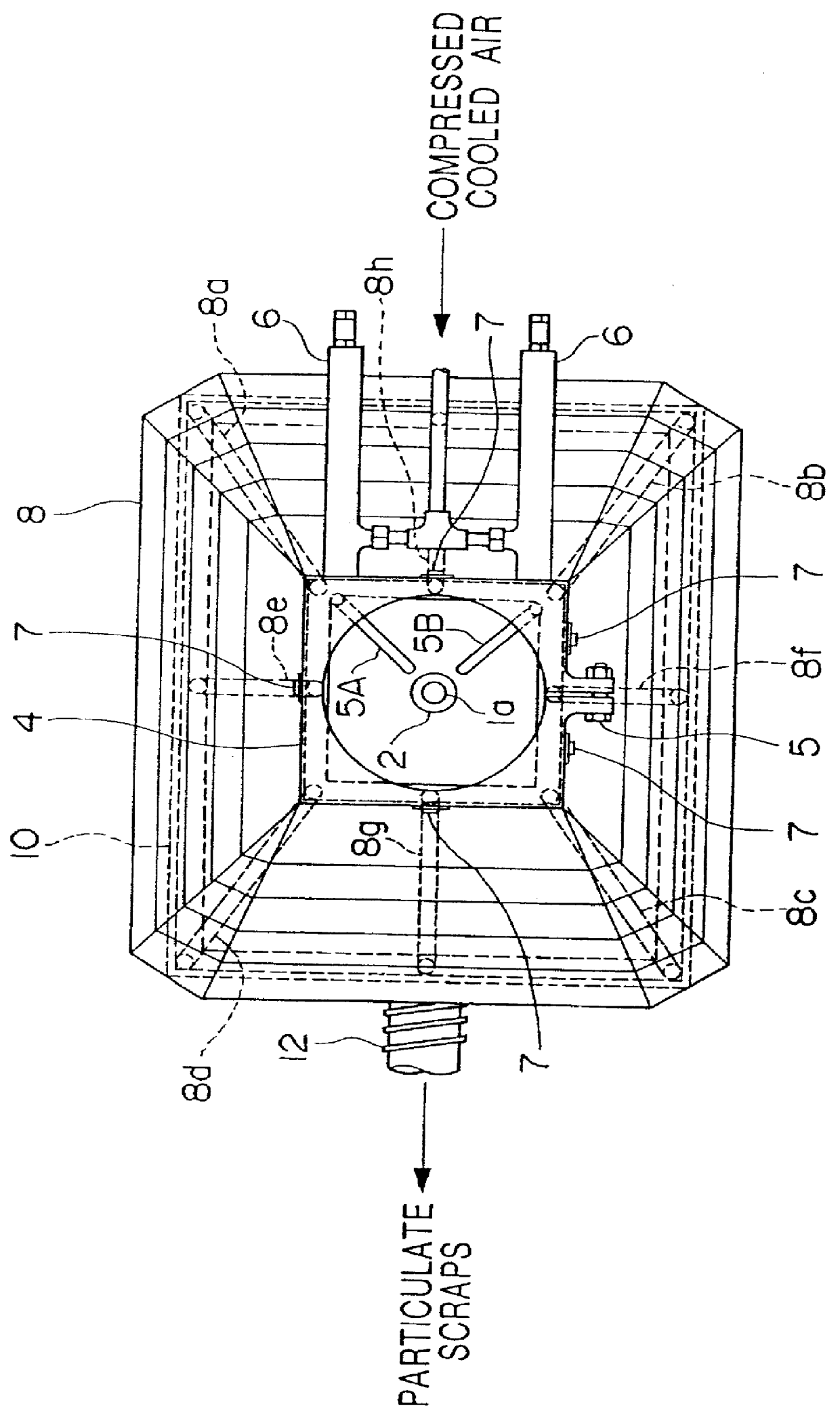
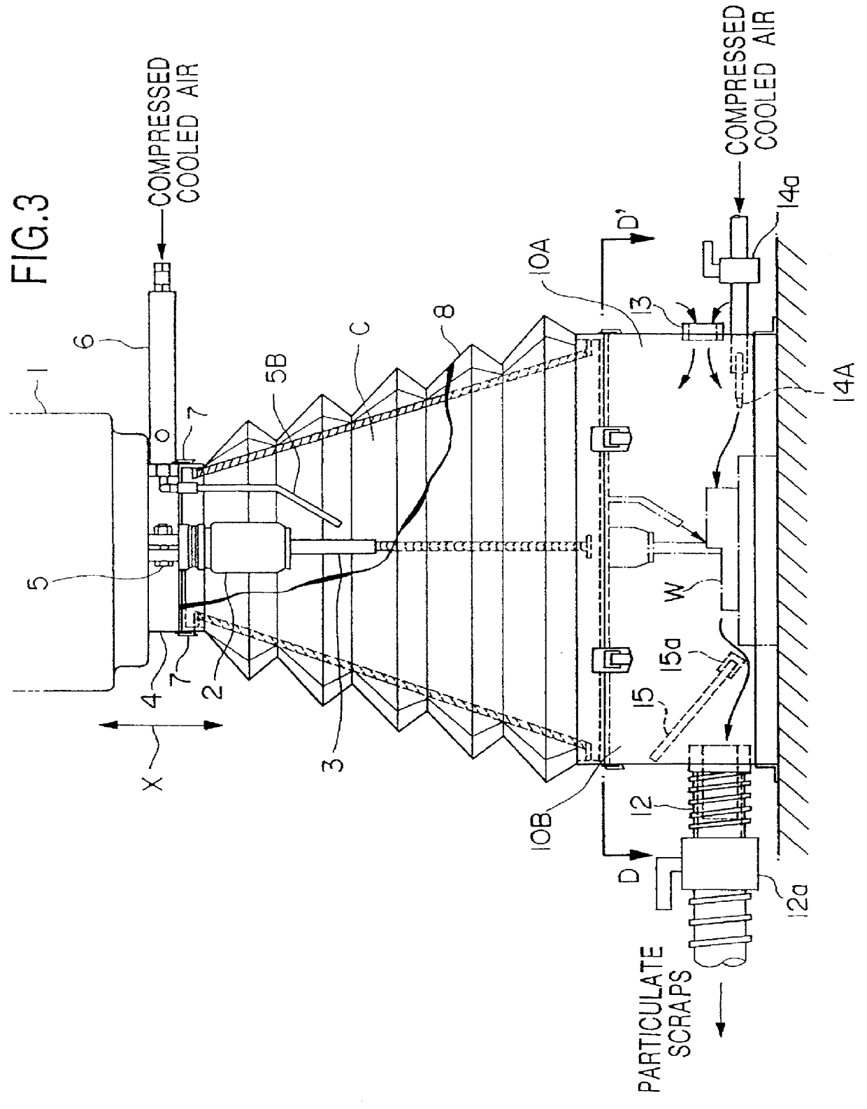
In these figures, numeral 1 is the spindle head, supported so as to be freely moving in the vertical direction, that is, the direction of the x arrow, and in the end part of the spindle 1a enclosed within it, cutter 3 is quick-release installed by holder 2. Also, at the lower part of spindle head 1, bracket 4 is held in place by screw 5, and at said bracket 4 two air nozzles 5A and 5B projecting towards cutter 3 are provided.

Said air nozzles 5A and 5B are disposed so as to blow compressed cooled air on cutter 3 from different directions, and can be freely bent so as to adjust the direction and height of blowing. In these air nozzles 5A and 5B, air coolers 6 connected to said air nozzles 5A and 5B are provided, and each air cooler 6 is provided with external compressed air.

At the lower part of the above-mentioned bracket 4, a bellow 8, which is a ...

second embodiment

B. The Second Embodiment

Next, the construction of the second embodiment of the present invention will be explained with reference to FIG. 3 and FIG. 4. Moreover, concerning the elements of the construction already explained in the above-described first embodiment, the same numerals will be used and the explanation omitted.

In these figures, numeral 13 is the external air intake opening, and is built facing the collecting duct 12 of the lower case 10B formed in the same manner as the above-mentioned lower case 10A. And in the inner space C, external air is brought in by said external air intake opening 13.

14A-14D are the compressed air nozzles, and are built opposite the collection duct 12 of the lower case 10B in the same manner as the external air intake opening 13, and the amount of the flow of the compressed air blown on the area of the work W can be adjusted by the airflow regulator valve 14a. Also, in this case, the air (including the particulate scraps) inside the inner space C...

third embodiment

C. The Third Embodiment

Next, the third embodiment of the machine tool of the present invention will be explained referring to FIG. 5. Moreover, this embodiment adds a device to the above-mentioned installation means, and the explanation of the elements of the construction already explained will be omitted.

In the above-mentioned embodiment, while bellow 8 and spindle head 1 are quick-release attached by the upper connecting member 7, in this embodiment an installation means which automatically performs said quick-release is constructed.

That is, numeral 20 is an air cylinder (drive means), and movable rod 20 a is fixed to the spindle head 1 in such a way as to move vertically in a perpendicular direction. The end of the movable rod 20a is fixed to the upper mounting metal fixture 21 which is fastened to the upper end of the bellow 8 by the floating joint 20b. 22A and 22B are guide bars disposed on both sides of the air cylinder 20, and fixed to the spindle head 1 by bowl bushing 23A a...


PUM

PropertyMeasurementUnit
circumferenceaaaaaaaaaa
elasticaaaaaaaaaa
magnetic forceaaaaaaaaaa

Abstract

PCT No. PCT/JP97/02496 Sec. 371 Date Mar. 3, 1998 Sec. 102(e) Date Mar. 3, 1998 PCT Filed Jul. 18, 1997 PCT Pub. No. WO98/03302 PCT Pub. Date Jan. 29, 1998In order to process a solid processed object with a simple construction, and to process a solid and flat work while effectively collecting particulate scraps, in a machine tool for processing work in which a working table on which the work is mounted and a spindle in which a cutter is installed move relatively to each other, a bellow which telescopes freely is provided, one open end of which connects to the spindle head so as to surround the spindle, and the other open end of which connects to a working table in such a manner as to surround the work.

Description

FIELD OF INDUSTRIAL APPLICATIONThe present invention relates to a machine tool which processes a work while collecting particulate scraps produced especially during processing.BACKGROUND TECHNOLOGYIn Japan, in the published Japanese Patent Application, First Publication No. Hei 6-55402 (Japanese Patent Application, Second Publication No. Hei 7-55437), a technology related to a cutter cooler and a particulate scrap collector in a processing machine is disclosed. In this conventional technology, by using a flexible hood, a cooling-collecting housing covering a cutter is brought into tight contact with the work, forming a closed space, and the particulate scraps produced by the processing are sucked up and collected by a vacuum particle suction apparatus connected to the cooling-collecting housing. Then, after blowing the cool air on the cutter, once the particulate scraps are blown upward off the cutter, they are and gathered in an exhaust duct.In addition, similarly in Japanese Paten...

Claims


Application Information

Patent Timeline
Patent Type & Authority Patents(United States)
IPC IPC(8): B23Q1/62B23Q11/00B23Q11/08B23Q11/10B23Q1/25
CPCB23Q1/621B23Q11/0042B23Q11/006B23Q11/0816B23Q11/0825B23Q11/10Y10T409/303976Y10T409/304088Y10T409/304032Y10T408/46Y10T408/50Y10T408/44B23Q11/1084Y10T83/207B23Q11/00B23Q11/08
Inventor SHONO, YOSHITAKA
Owner TOKO KABUSHIKI KAISHA
Why Eureka
Try Eureka