Batch-type kiln

a batch type, kiln technology, applied in muffle furnaces, furnaces, furnaces, etc., can solve problems such as electrical leakage, tar accumulation, and other problems, and achieve the effect of reducing heat insulation, reducing heat insulation, and reducing the amount of tar

Inactive Publication Date: 2001-01-02
MURATA MFG CO LTD
View PDF12 Cites 13 Cited by
  • Summary
  • Abstract
  • Description
  • Claims
  • Application Information

AI Technical Summary

Problems solved by technology

However, in so treating the ceramic product in conventional batch-type kilns, the treatment of an organic binder produced during dewaxing becomes a problem.
As a result of this relatively low temperature in the gap, the gas produced from binder decomposition which flows therethrough liquefies or solidifies, accumulating as tar which produces an offensive smell.
This effect can result in reduced heat insulation, electrical leakage, or other problems.

Method used


Image

  • Batch-type kiln
  • Batch-type kiln
  • Batch-type kiln

Examples


Embodiment Construction

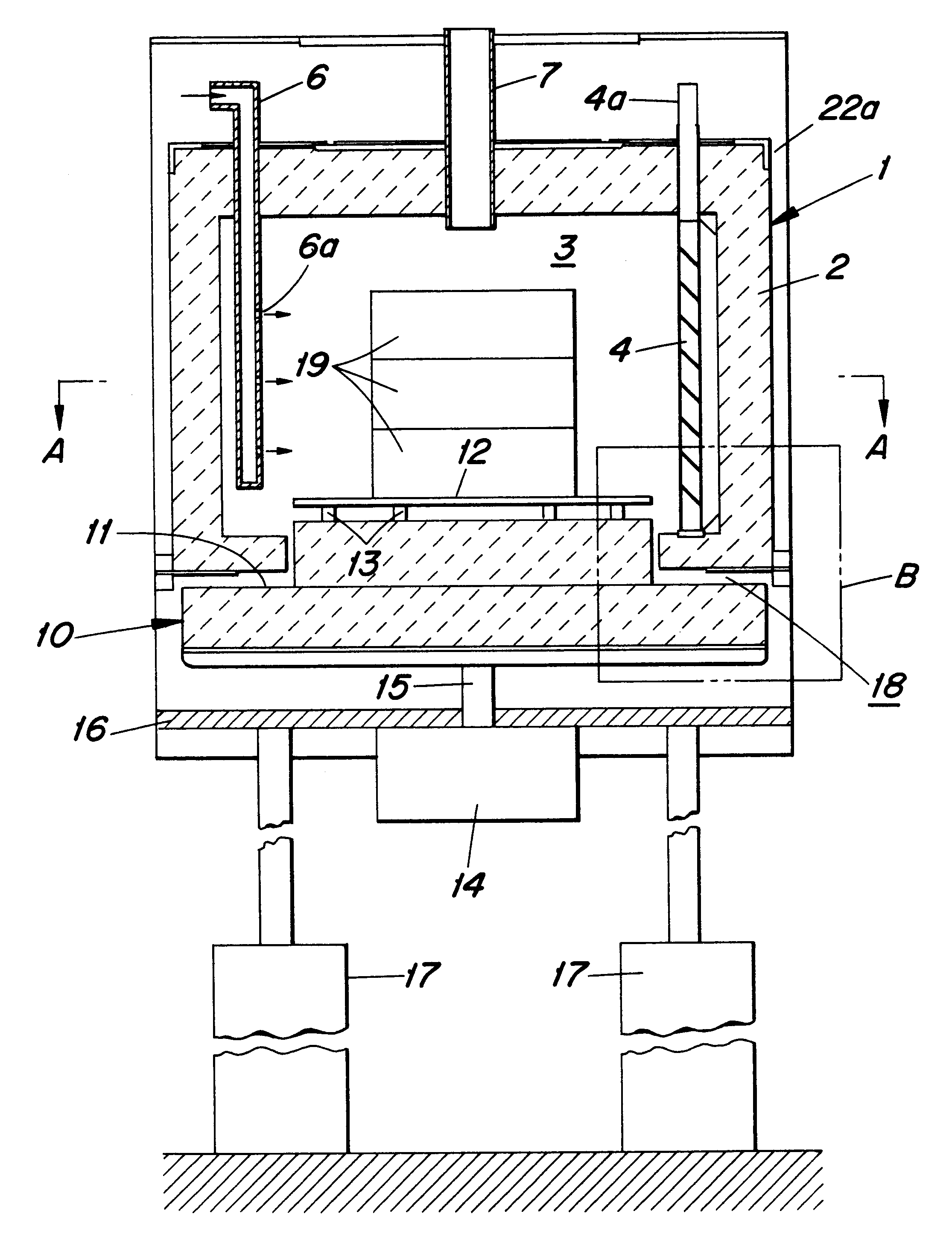
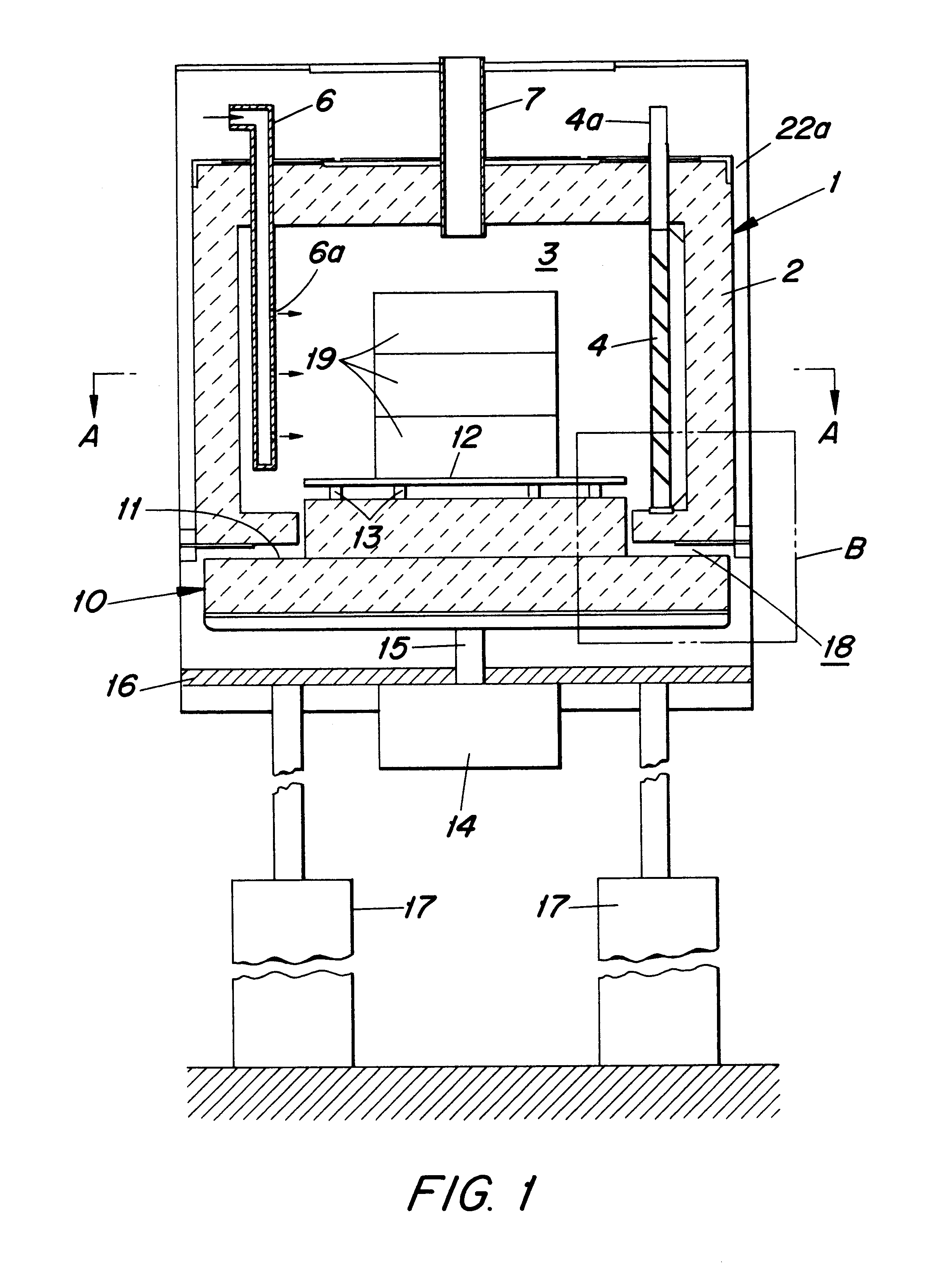
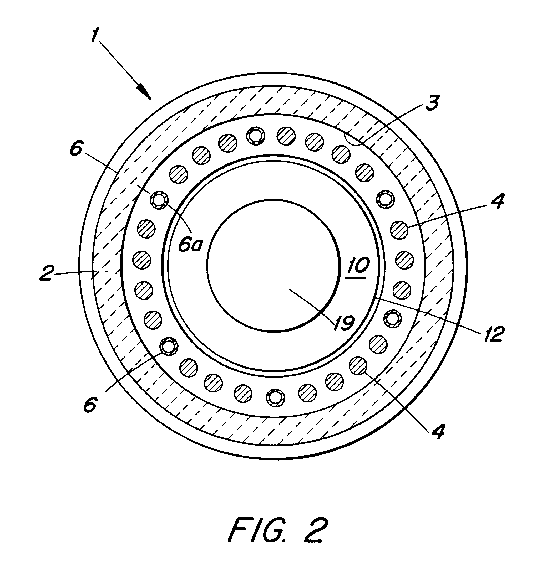
With reference to FIGS. 1 to 3, one embodiment of a batch-type kiln in accordance with the present invention will be described.

The batch-type kiln comprises a cylindrical kiln body 1 having an opening at the bottom portion thereof and formed by a heat-resistant member 2 made of, for example, ceramic brick or felt. The kiln further includes a heating chamber 3, which has a plurality of spiral heaters 4 disposed in a concentric manner with heating chamber 3. Spiral heaters 4 pass through the ceiling of kiln body 1, and are inserted into heating chamber 3 through the upper wall of chamber 3.

Spiral heaters 4 are covered along their respective outer peripheries with a heat-resistant insulating tube 5, except for a terminal portion 4a of the heaters. Tube 5 can be constructed of a material which does not allow penetration of a binder component or the like, such as fine alumina or silica ceramic. The bottom end opening of tube 5 butts against the bottom portion of kiln body 1. In this way,...


PUM


Abstract

A novel batch-type kiln and a method of use thereof are provided. The kiln comprises a kiln body and a heating chamber disposed within the kiln body, which has a heater disposed therein. A table is disposed at the bottom of the heating chamber, the table having a peripheral portion and an upper surface for supporting an object to be treated. The peripheral portion of the table and a portion of the kiln body define a gap therebetween. This gap forms a gas-introducing path for introducing a gas into the heating chamber. The batch-type kiln is capable of preventing accumulation of a binder component in the gap between the table and the kiln wall.

Description

This application is based on Japanese Priority Application Hei 8-56944, the contents of which are hereby incorporated by reference.1. Field of the InventionThe present invention relates a batch-type kiln having particular applicability in the performance of firing treatments, such as a dewaxing step and a firing step, on a ceramic product, such as a ceramic capacitor.2. Description of the Related ArtConventional batch-type kilns comprise a heating chamber and a table. The heating chamber is formed by placing a rod-shaped or U-shaped heater within a box-shaped or cylindrical kiln body. A table is disposed at the bottom portion of the heating chamber and is capable of being raised and lowered. A sagger containing a ceramic product is placed on the table, and the table is raised to place the sagger into the heating chamber for firing treatment. Upon completion of the treatment, the table is lowered and the sagger is removed from the kiln.Conventionally, dewaxing and firing steps are su...

Claims


Application Information

Patent Timeline
Patent Type & Authority Patents(United States)
IPC IPC(8): F27B17/00F27D9/00F27D23/00F27D3/00F27D7/00F27D7/02F27D99/00
CPCF27B17/0016F27D9/00F27D7/02F27D2003/0075F27D2009/0005F27D2099/0008
Inventor YAMADA, YOSHITSUGU
Owner MURATA MFG CO LTD
Why Eureka
Try Eureka