Recirculating air mixer and fan with lateral air flow

a technology of air mixer and fan, which is applied in ventilation systems, heating types, separation processes, etc., can solve the problems of not being able to achieve effective solutions, grilles have had some success, and the direct flow of heated or cooled air can be quite uncomfortabl

Inactive Publication Date: 2001-01-02
COOK E F
View PDF2 Cites 115 Cited by
  • Summary
  • Abstract
  • Description
  • Claims
  • Application Information

AI Technical Summary

Problems solved by technology

As anyone knows who has had the misfortune to have been seated at a desk or table directly underneath a ventilating duct, being subjected to direct flow of heated or cooled air can be quite uncomfortable.
Similar problems were encountered where a ceiling vent was positioned above one side of a doorway.
Such grills have had some success, but often are not an effective solution, because they tend merely to redirect the airflow to a neighboring location.
In addition, many of the downwardly directed air vents have little effect in mixing the air in an office, restaurant or other similar large enclosure.
However, that dispersion is gradual and does not create any strong air currents which would be uncomfortable to those people within the room.

Method used


Image

  • Recirculating air mixer and fan with lateral air flow
  • Recirculating air mixer and fan with lateral air flow
  • Recirculating air mixer and fan with lateral air flow

Examples


Embodiment Construction

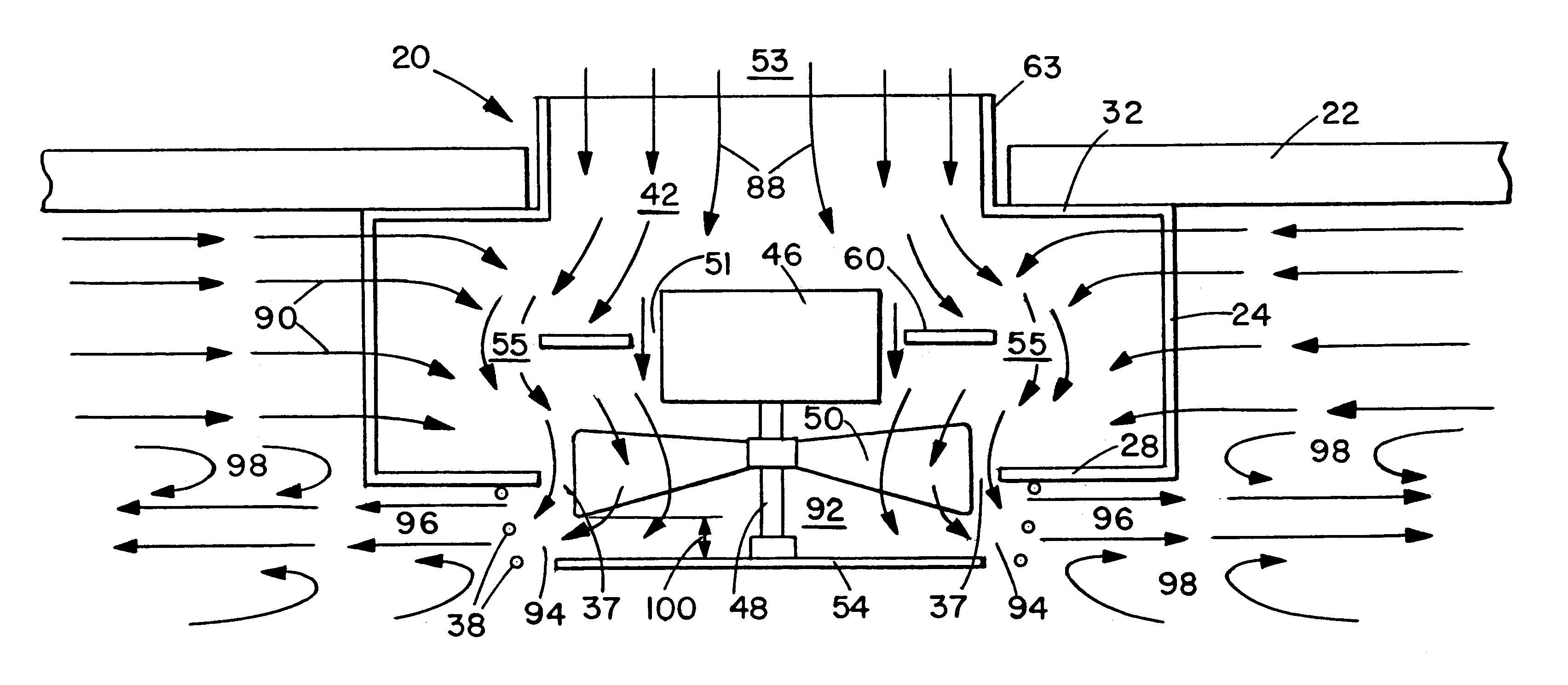
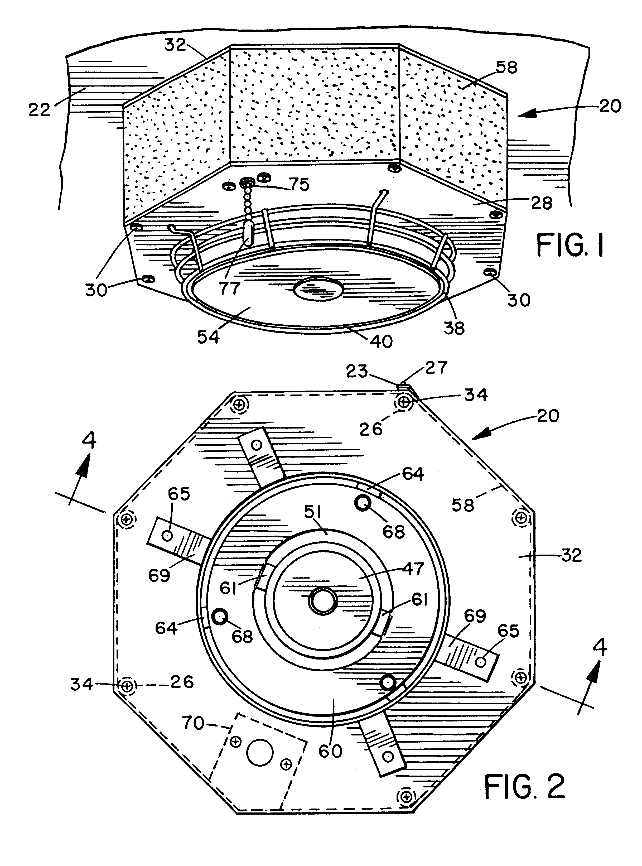
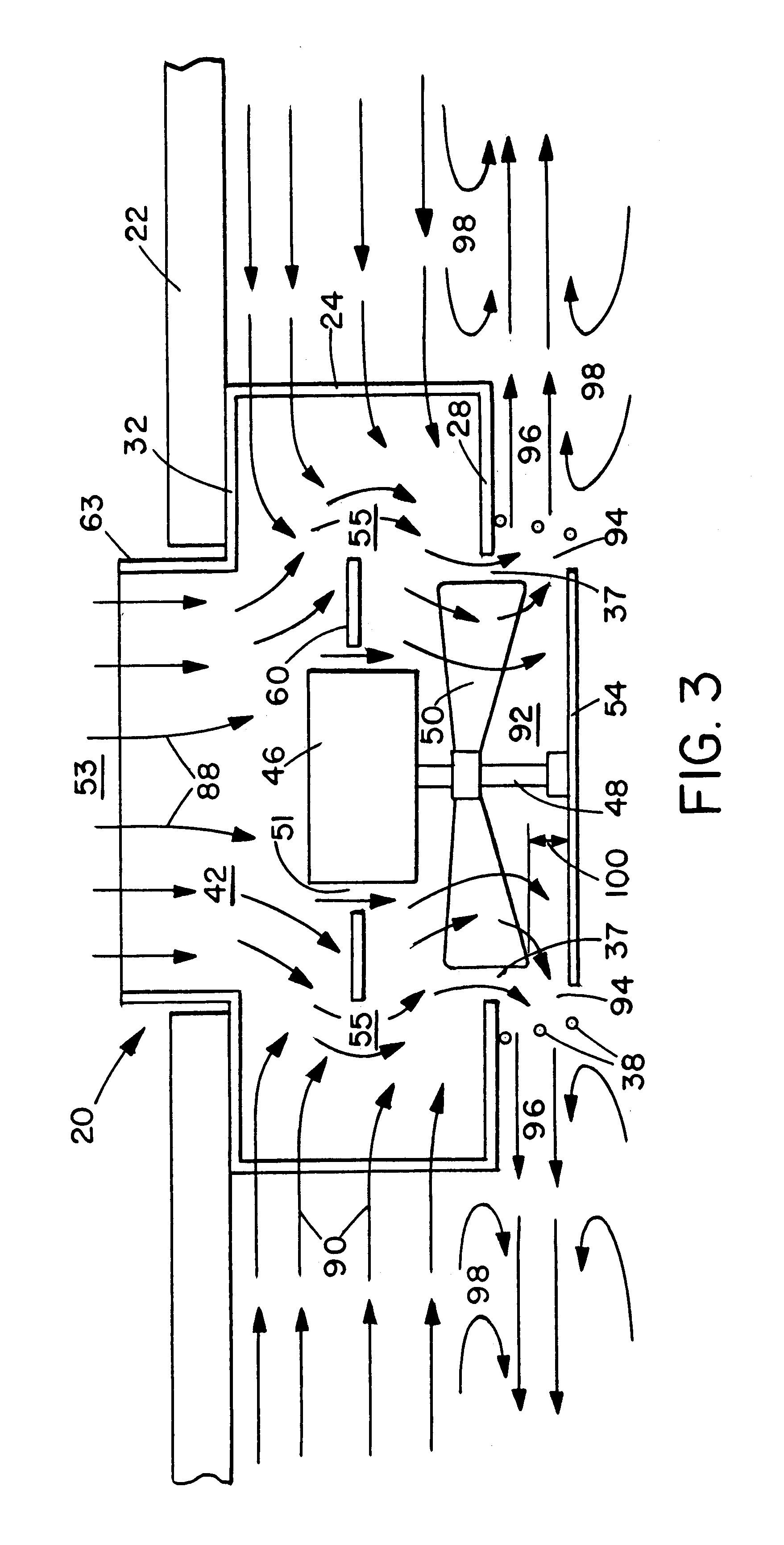
The invention is best understood by reference to the drawings. For clarity in discussion, it will be assumed unless otherwise stated that the device of this invention is disposed horizontally attached to a ceiling, i.e., in the orientation shown in FIGS. 1 and 3-5, so that the fan blades 50 and disk 54 rotate in a substantially horizontal plane. Vertical orientation is exemplified by attachment to a wall, as will be discussed below with reference to FIG. 7. "Downwardly" and "upwardly" will be with respect to horizontal orientation.

FIGS. 1, 2 and 4 show a device 20 of the present invention, with FIG. 1 showing it in the horizontal orientation as it would be observed by someone standing on the floor when the device is mounted on a ceiling 22. It is formed of an open frame 24 which is made of vertical bars 26 which are attached at their lower ends to a bottom plate 28 by screws 30 and at their upper ends to a mounting plate 32 by screws 34. The bottom plate 28 has a first central apert...


PUM

PropertyMeasurementUnit
vertical distanceaaaaaaaaaa
areaaaaaaaaaaa
areaaaaaaaaaaa

Abstract

An air circulation and mixing device is disclosed which can cover a ceiling air ventilation duct, taking air discharged from the duct and drawing air at the room's ceiling, mixing the two, and redirecting the mixed air so that it is discharged radially and parallel to the ceiling, rather than directly downwardly. The device has an open frame whose sides may be covered with removable air filtration media and which forms a primary interior having a lower aperture and normally an upper aperture. An open-sided grille below the lower aperture forms a secondary space. A fan is mounted within the primary space and turns blades within the lower aperture and a disk at the bottom of the secondary space. An annular plate surrounding the fan housing blocks downward flow of incoming air and forces the air to flow radially outwardly around the edge of the plate, thus also insuring good mixing with the incoming ceiling air. The rotating disk receives air blown downwardly through the lower aperture and redirects it radially outwardly through the openings in the side of the grille, such that airflow becomes horizontal and parallel to the ceiling, so that the air flow slows and the air becomes gradually dispersed throughout the entire room. The device can also be mounted over a through-wall air duct outlet by using a duct extension.

Description

1. Field of the InventionThe invention herein relates to air movement and circulation devices such as fans, mixers and blowers. More particularly it relates to such devices for mixing and direction of air from ventilation systems and within confined spaces such as rooms in homes or offices.2. Description of the Prior ArtIn most offices, stores, restaurants and similar buildings air ventilation is obtained through forced air ducts in the ceiling which carry high-volume air streams, with the air being heated or cooled according to the season of the year and the activity occurring in that ventilated portion of the building. The same type of system is used in many homes and apartments, but the volume of airflow is generally less.As anyone knows who has had the misfortune to have been seated at a desk or table directly underneath a ventilating duct, being subjected to direct flow of heated or cooled air can be quite uncomfortable. While in some cases it may be possible to move away from ...

Claims


Application Information

Patent Timeline
Patent Type & Authority Patents(United States)
IPC IPC(8): F24F13/04F24F7/007
CPCF24F7/007F24F13/04F24F2003/1614F24F2221/14F24F8/108Y02A50/20
Inventor COOK, E. F.
Owner COOK E F
Why Eureka
Try Eureka