Trailer hitch positioning system

a technology for trailer hitches and positioning systems, which is applied in the direction of transportation and packaging, instruments, sport apparatus, etc., can solve the problems of difficulty in positioning the ball of the trailer hitch beneath the tongue of the trailer

Inactive Publication Date: 2001-01-30
THIBODEAUX JOSEPH I
View PDF28 Cites 125 Cited by
  • Summary
  • Abstract
  • Description
  • Claims
  • Application Information

AI Technical Summary

Problems solved by technology

Many individuals find it difficult to position the ball of a trailer hitch be...

Method used


Image

  • Trailer hitch positioning system
  • Trailer hitch positioning system
  • Trailer hitch positioning system

Examples


Embodiment Construction

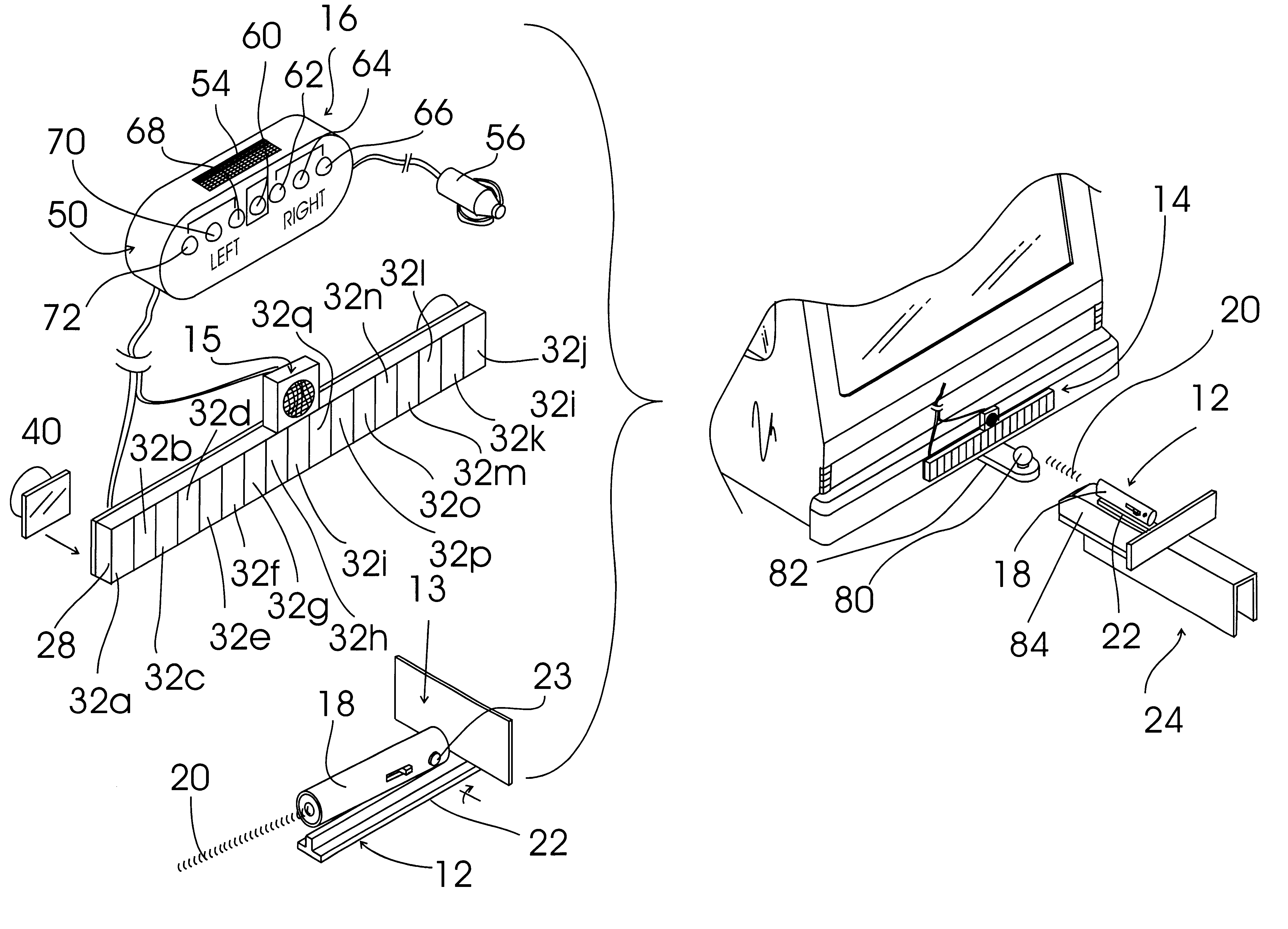
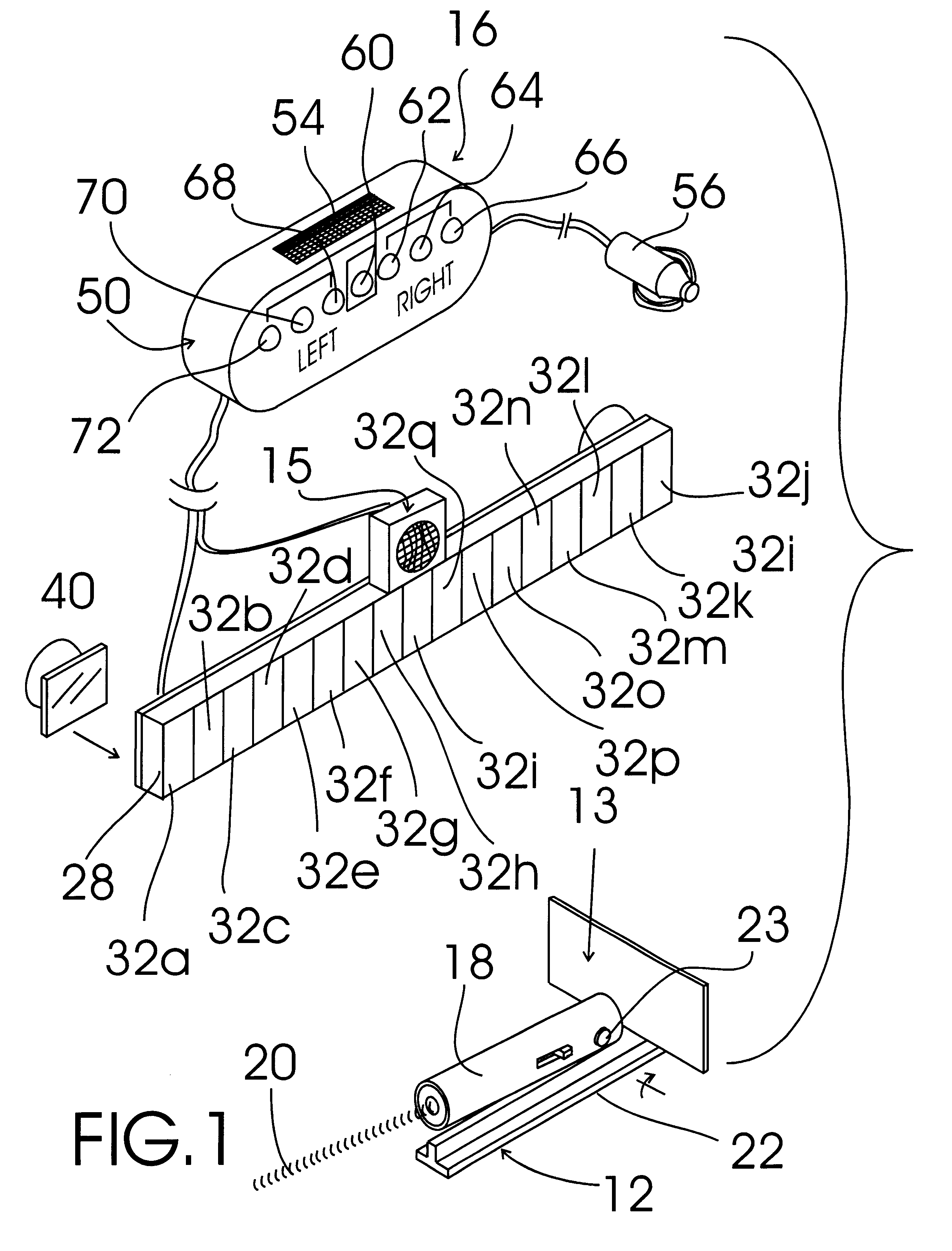
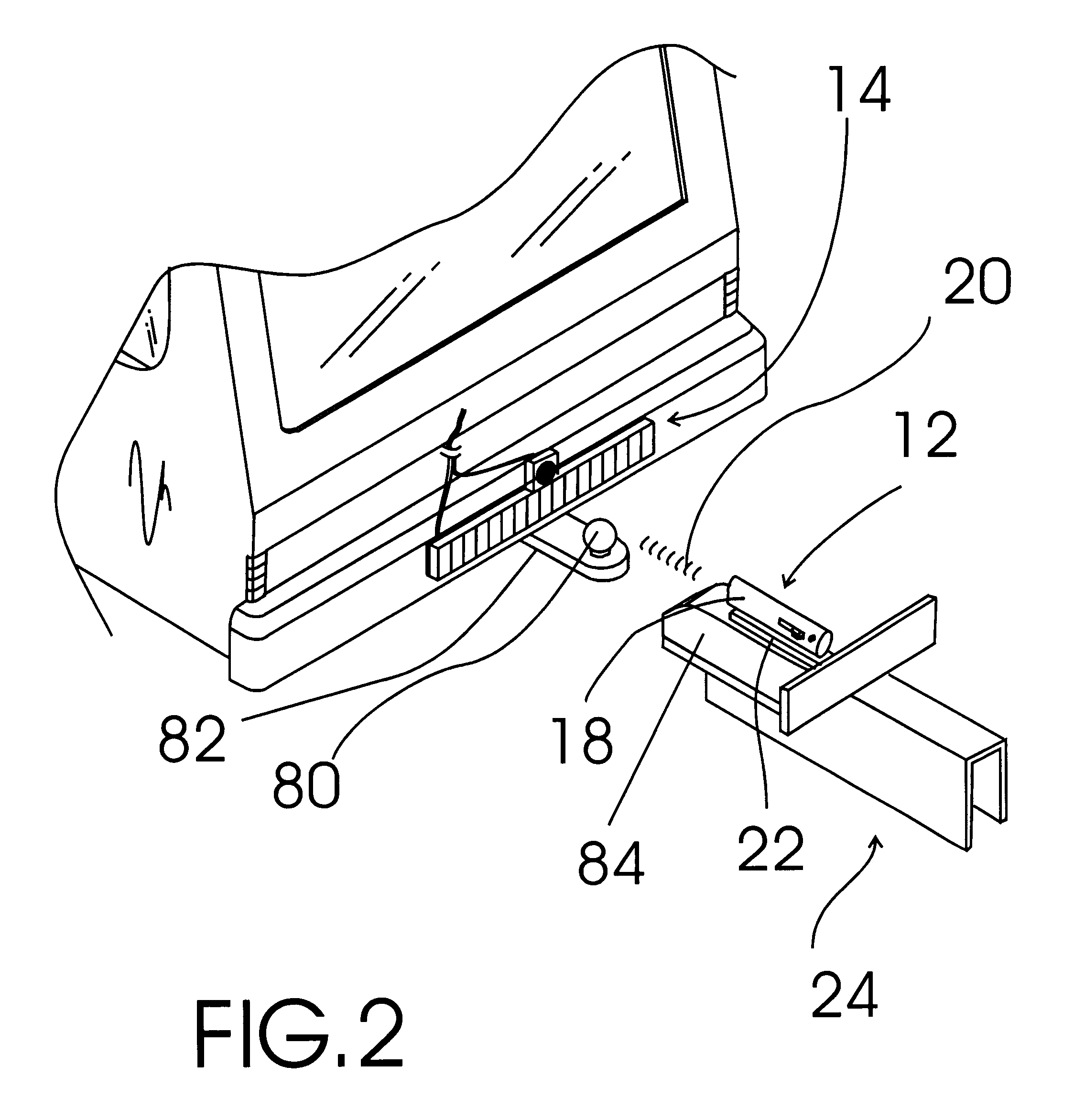
FIG. 1 shows an exemplary embodiment of the trailer hitch positioning system of the present invention generally designated 10. Trailer hitch positioning system 10 includes a pinpoint light source assembly, generally designated 12; a proximity sensor reflector plate, generally designated 13; a light beam sensing array assembly, generally designated 14; a sonic proximity sensor, generally designated 15; and a passenger compartment display unit, generally designated 16. Pinpoint light source assembly 12 includes a conventional laser diode pointer pinpoint light source 18 that provides a pinpoint light beam 20 and that is pivotally mounted with a pivot pin 23 to a magnetic light source base 22 that, with reference to FIG. 2, is used to attach pinpoint light source assembly 12 to the tongue portion 24 of a trailer. Proximity sensor reflector plate 13 is a metal plate secured perpendicularly to the back end of magnetic light source base 22. Pivotally mounting the pinpoint light source 18 ...


PUM


Abstract

A trailer hitch positioning system that provides a visual and an audible indication to a vehicle driver of the position of the trailer ball with respect to the tongue of the trailer. The trailer hitch positioning system includes a pinpoint light source assembly, a light beam sensing array assembly, and a passenger compartment display unit wherein a pinpoint beam from the pinpoint light source assembly strikes and activates light beam sensors within the light beam sensing array assembly, the activations of the light beam sensors being detected by a digital controller within the display unit which then provides a corresponding positional information output to the vehicle driver through an LED display and an audible alerting buzzer.

Description

The present invention relates to trailer / vehicle connecting aids and more particularly to a trailer hitch positioning system that includes a pinpoint light source assembly, a light beam sensing array assembly, a sonic proximity sensor, a proximity sensor reflector plate and a passenger compartment display unit wherein a pinpoint beam from the pinpoint light source assembly strikes and activates light beam sensors within the light beam sensing array assembly, the activations of the light beam sensors being detected by a digital controller within the display unit which then provides a corresponding positional information output to the vehicle driver through an LED display, the sonic proximity sensor being in connection with the digital controller and emitting and receiving sonic signals toward and from the proximity sensor reflector plate to determine the distance between the sonic proximity sensor and the proximity sensor reflector plate, the digital controller receiving a distance s...

Claims


Application Information

Patent Timeline
IPC IPC(8): B60D1/00B60D1/36
CPCB60D1/36
Inventor THIBODEAUX, JOSEPH I.
Owner THIBODEAUX JOSEPH I
Why Eureka
Try Eureka