Key retaining lock apparatus

a lock and key technology, applied in the field of lock devices, can solve the problems of abuse of free firewood, all available wood is too wet to readily burn, and one-half of the firewood provided to campers is either stolen or wasted, so as to facilitate the sale of dry firewood, promote the use of firewood judiciously, and stop theft

Inactive Publication Date: 2001-01-30
GLAZIER JAMES F
View PDF10 Cites 31 Cited by
  • Summary
  • Abstract
  • Description
  • Claims
  • Application Information

AI Technical Summary

Benefits of technology

It is an object of this invention to disclose a lock apparatus which will freeze in an open (or closed) position and retain the key therein. It is an object of this invention to disclose a lock apparatus which may be used in a dispensing box so that the key to the dispensing box may be delivered to the buyer at the time of sale. More specifically it is an object of this invention to facilitate the sale of dry fire wood in parks. When the sale of wood is made the key to a full box of wood will be delivered to the buyer. Upon use, the key will be snagged in the lock and the lock will be frozen open. It is yet a further object of this invention to stop theft and promote the judicious use of fire wood through a convenient vending apparatus which will facilitate sales therefrom. It is a final object of this invention to disclose a key retaining lock which may be used to facilitate and monitor the vending of particularly difficult to handle products delivered to the point of use.

Problems solved by technology

The provision of free firewood is being abused.
Park managers believe that one half of the firewood provided to campers is either stolen or wasted.
Another problem is that during wet periods--when firewood is most needed--all of the wood available is too wet to readily burn.

Method used


Image

  • Key retaining lock apparatus
  • Key retaining lock apparatus

Examples


Embodiment Construction

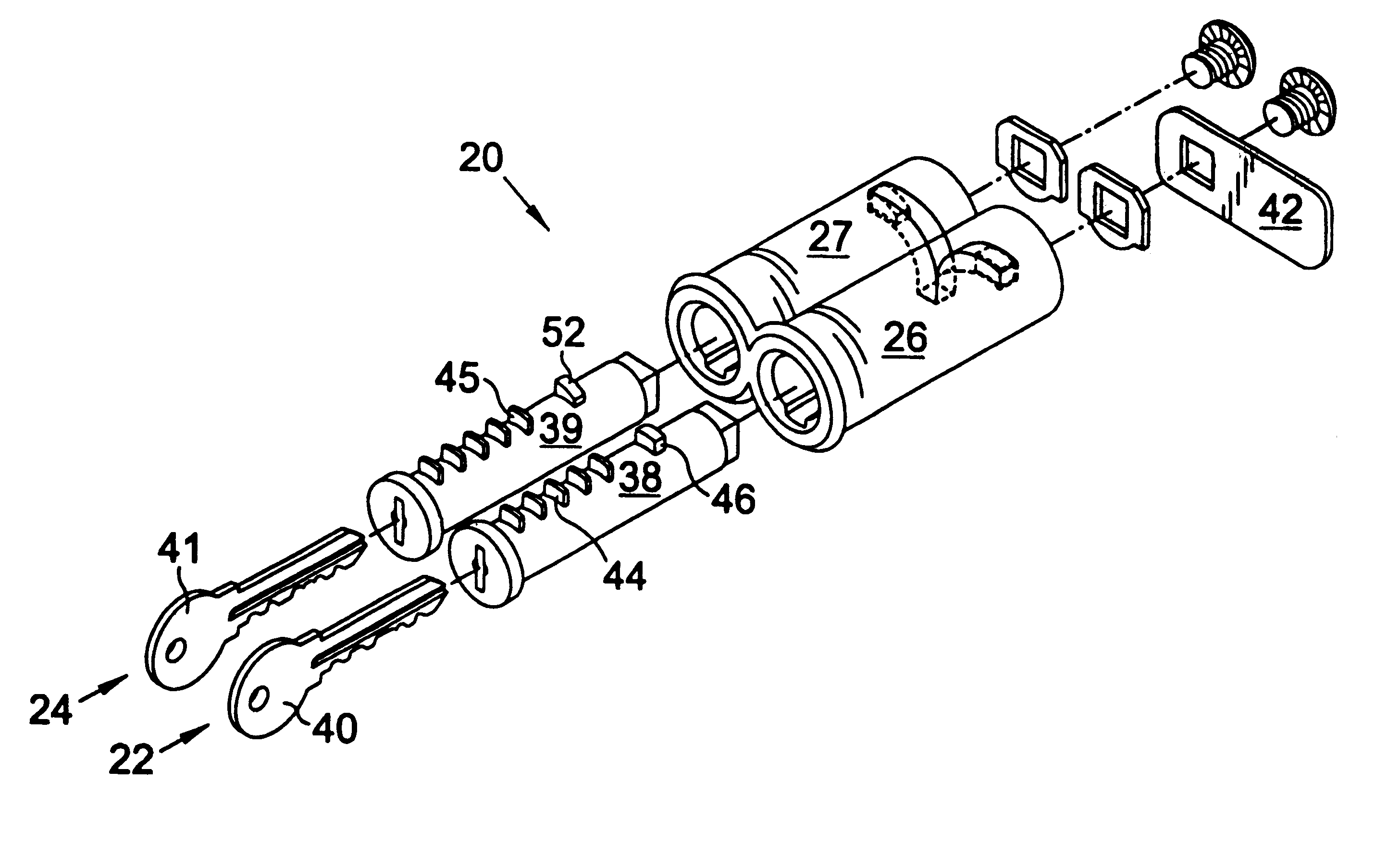
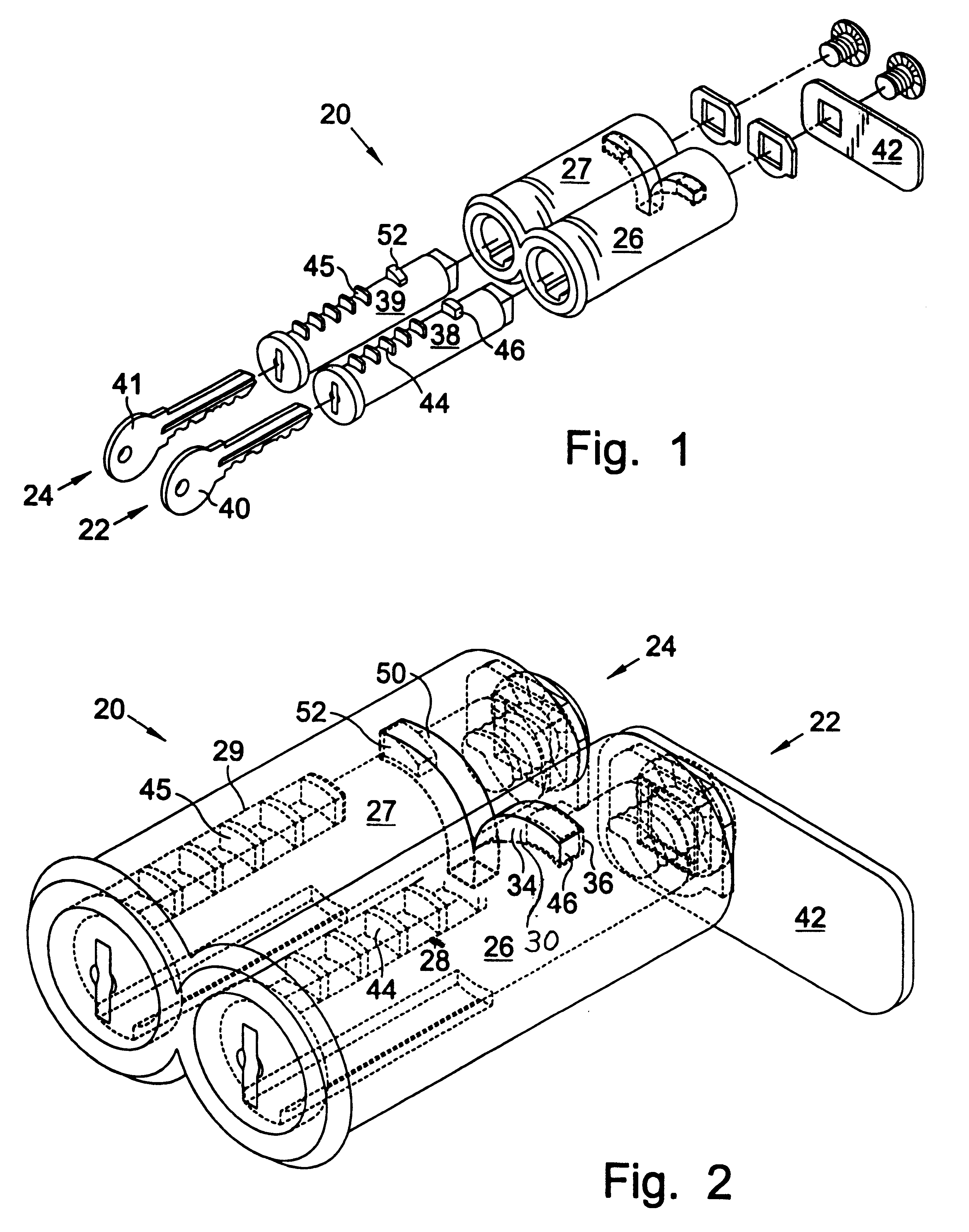
Turning now to the drawings and more particularly to FIG. 1 we have an exploded perspective view of a key retaining lock apparatus 20. FIG. 2 is an assembled view of the portion of the key retaining lock apparatus 20 which would be mounted in a swinging door (not shown). The key retaining lock apparatus 20 comprises two locks, a first key snag lock 22 which is used to open a door (not shown), and a second release lock 24, which is used to release the key snag lock 22. The first key snag lock has a barrel 26 having an interior longitudinal slot 28, and a ramped circumferential groove segment 30 having a shallow 34 and deep end portion 36; a tumbler 38 within the barrel 26; a key 40; a radial catch arm 42 connected to a rear portion of the tumbler 38; locking wafers 44 in the tumbler 38 slidingly projecting into the longitudinal slot 28 which are fully retracted when the key 40 is fully inserted into the tumbler 38 so that the tumbler 38 may be rotated turning the catch arm 42; and, a...


PUM


Abstract

An apparatus having two barrel and tumbler locks which are longitudinally overlapped and conjoined to operate in combination with each other. When the first lock is moved to an open position it becomes frozen with the key snagged therein. The second lock is used to unfreeze and release the key from the first lock. Both locks are of the type having a barrel and tumbler. The first lock has a barrel having a ramped circumferential groove segment having a shallow end portion. A groove wafer extends from the tumbler into this groove. The second release lock has a circumferential groove segment in its barrel similarly having a groove wafer extending from the tumbler into this groove. The groove segments are arranged so that the shallow end portion of the first ramped groove segment meets an end portion of the groove on the second lock so that when the first lock is rotated from a closed position to an open position its groove wafer moves from the ramped groove downwardly into the groove segment in the second barrel, thereby preventing the barrel from being rotated back to an open position to release its key. The first lock may only be released when the groove wafer in the second lock is used to push the first groove wafer out of the groove segment in the second barrel.

Description

This invention relates to locks which retain the keys which open them. More particularly invention relates to an apparatus having two barrel and tumbler locks which operate in combination with each other. When the first lock is moved to an open position it becomes frozen with the key snagged therein. The second lock is used to unfreeze and release the key from the first lock.National and provincial government parks in Canada currently supply fire wood at no additional cost to campers when it is available from trees that have been removed. The provision of free firewood is being abused. Park managers believe that one half of the firewood provided to campers is either stolen or wasted. Another problem is that during wet periods--when firewood is most needed--all of the wood available is too wet to readily burn.OBJECTS AND STATEMENT OF INVENTIONIt is an object of this invention to disclose a lock apparatus which will freeze in an open (or closed) position and retain the key therein. It...

Claims


Application Information

Patent Timeline
Patent Type & Authority Patents(United States)
IPC IPC(8): E05B35/00E05B35/08
CPCE05B35/086Y10S70/63
Inventor GLAZIER, JAMES F.
Owner GLAZIER JAMES F
Why Eureka
Try Eureka