Camera capable of correcting camera-shake

a camera and detector technology, applied in the field of cameras, can solve the problems of taking time for the camera-shake sensor to become able, producing blurred pictures, etc., and achieve the effect of avoiding unnecessary driving of the taking lens and reliable unblurred pictures

Inactive Publication Date: 2001-01-30
MINOLTA CO LTD
View PDF17 Cites 24 Cited by
  • Summary
  • Abstract
  • Description
  • Claims
  • Application Information

AI Technical Summary

Benefits of technology

Camera-shake detecting means can not detect camera-shake amount immediately after a signal for starting its operation is entered. Therefore, when such a camera-shake detector is in an inoperable state, a warning that the camera can not make camera-shake correction is displayed at a warning display portion. Then, a photographer can recognize that the camera-shake correction device is not operating and thus, does not start photographing until output of the camera-shake sensor is stabilized. As a result, it becomes possible to take reliably unblurred pictures using the camera with a camera-shake sensor.
In a camera according to the present invention, lens driving for camera-shake correction is detected when the camera-shake amount is large in the out-of-focus state. When the camera-shake amount is large in the out-of-focus state, the in-focus state can not be easily realized even if a taking lens is driven. According to the present invention, driving of a taking lens is inhibited when the camera-shake amount is large in the out-of-focus state. Therefore, unnecessary driving of the taking lens is eliminated in the camera with a camera-shake sensor.

Problems solved by technology

However, it takes time for the camera-shake sensors to become able to provide stable output of camera-shake detection after the sensors are turned on.
As a result, even those cameras provided with camera-shake-sensors and correction mechanism may produce blurred pictures without operating such mechanism in such a case.

Method used


Image

  • Camera capable of correcting camera-shake
  • Camera capable of correcting camera-shake
  • Camera capable of correcting camera-shake

Examples


Embodiment Construction

In the following, embodiments of the present invention will be described with reference to the accompanying drawings. Meanwhile, the description below is made not only on system of the present invention but on the entire system including those parts or functions that have no direct relation with the present invention.

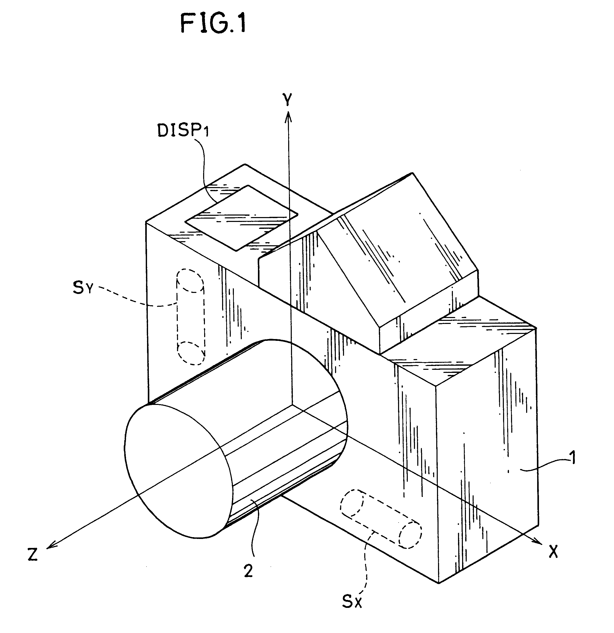
FIG. 1 is a schematical perspective view of a camera having a camera-shake detecting sensor according to the present invention. Referring to FIG. 1, the camera according to the present invention comprises camera body 1 and lens 2 interchangeably provided to camera body 1. Camera body 1 comprises X direction camera-shake sensor Sx for detecting camera-shake amount in the X direction in the figure, Y direction camera-shake sensor Sy for detecting camera-shake amount in the Y direction, and display portion DISP.sub.1 for giving a warning when X direction and Y direction camera-shake sensors Sx and Sy are not in the operating state.

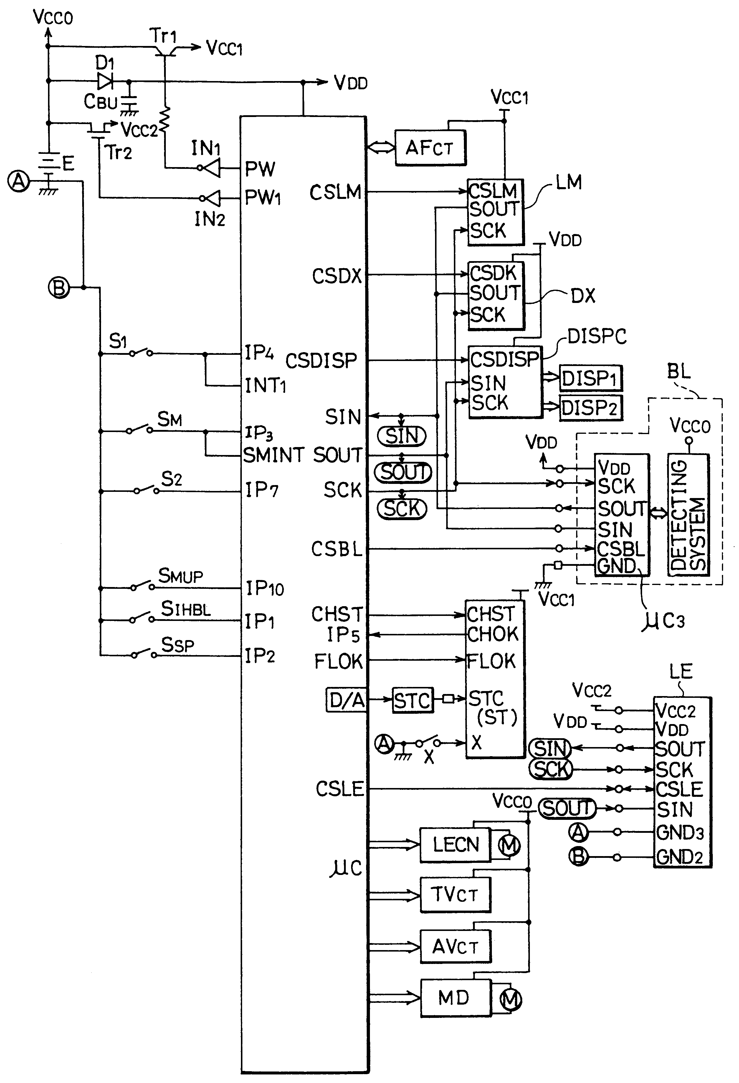
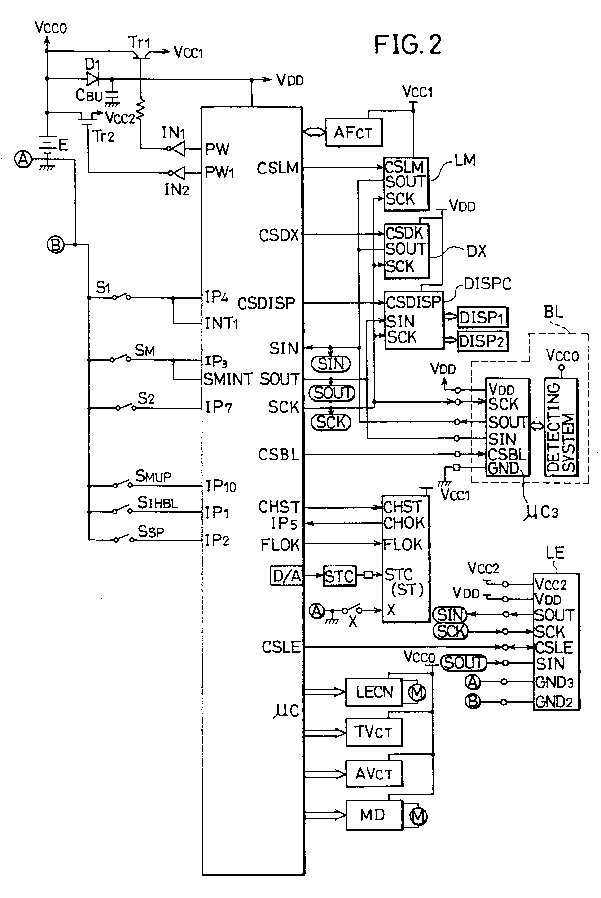
FIG. 2 is a block diagram showing a circui...


PUM


Abstract

A camera comprises an angular velocity sensor for detecting camera-shake. The angular velocity sensor takes a certain time to be stabilized after its operation is started. When correction of camera-shake is required during the certain period, it is displayed that correction of camera-shake is not possible. As a result, a photographer using the camera with the camera-shake detection sensor refrains from photographing when correction of camera-shake is not possible.

Description

BACKGROUND OF THE INVENTION1. Field of the InventionThe present invention generally relates to cameras, and more particularly, to a camera having a camera-shake detector which detects camera-shake occurring when a picture is taken.2. Description of the Related ArtsSome conventional cameras have been proposed with camera-shake detecting sensors which detect camera-shake to prevent pictures being blurred. A conventional camera provided with a camera-shake detecting sensor comprises a camera-shake detecting sensor, a correcting device for correcting camera-shake amount in response to output of detection, and a display unit for making display of a warning that a picture is being blurred.A conventional camera which can correct camera-shake is responsive to output of camera-shake detecting sensor for correcting camera-shake amount so as to allow unblurred pictures to be taken and at the same time, display that unblurred picture are being taken.Conventional cameras with camera-shake sensor...

Claims


Application Information

Patent Timeline
Patent Type & Authority Patents(United States)
IPC IPC(8): G03B5/00G02B27/64G03B17/12G03B17/14G03B17/18
CPCG02B27/646G03B5/00G03B17/14G03B2205/0007G03B2217/005G03B2217/185
Inventor HAMADA, MASATAKAMASUMOTO, HISAYUKIOKADA, TAKASHIOOTSUKA, HIROSHI
Owner MINOLTA CO LTD
Why Eureka
Try Eureka