Bending device and bending method

a bending device and a technology of bending method, applied in the direction of shaping safety devices, metal-working feeding devices, manufacturing tools, etc., can solve the problems of long time needed for working, inability to bend as designed, and inability to easily know which bending to perform

Inactive Publication Date: 2001-02-13
OPTON KK
View PDF9 Cites 20 Cited by
  • Summary
  • Abstract
  • Description
  • Claims
  • Application Information

AI Technical Summary

Problems solved by technology

After the movement, each joint of the joint type robot is rotated to move the bending mechanism in such a manner that the work is placed between the bending die and the clamping die of the bending mechanism, which causes a problem that the time necessary for working is lengthened.
When the work is bent in accordance with design data, in most cases, the work cannot be bent as designed because of differences in hardness and elongation of the work.
Moreover, since there are a large number

Method used


Image

  • Bending device and bending method
  • Bending device and bending method
  • Bending device and bending method

Examples


Embodiment Construction

An embodiment of the present invention will be described hereinafter in detail with reference to the drawings.

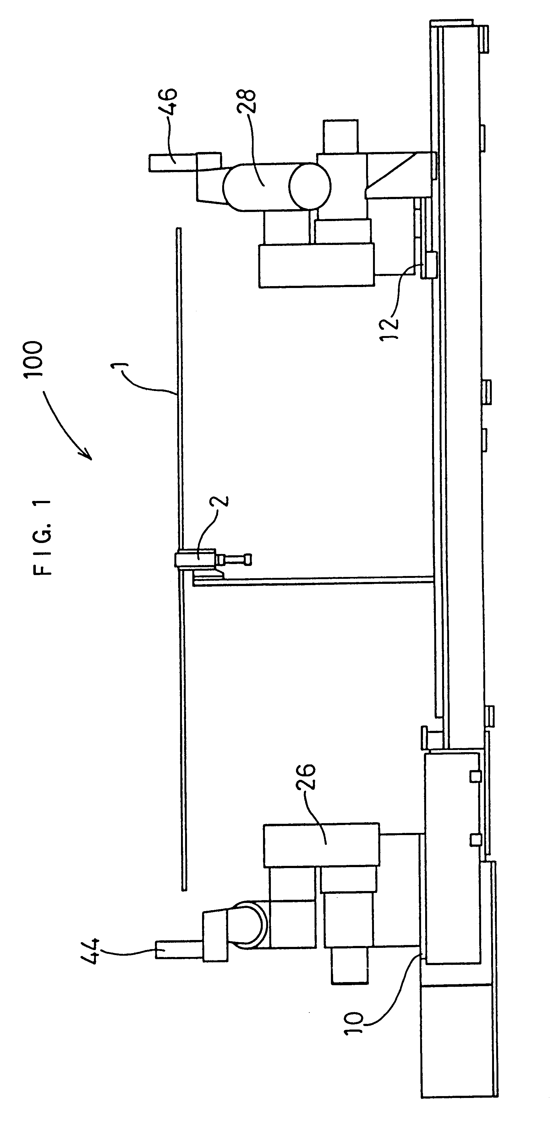
As shown in FIG. 1, a chuch mechanism 2 which can hold a pipe or a longitdinal work 1 is provided substantially in the center of a bending device 100. In the chuck mechanism 2, the outer periphery of the work 1 is held by chucks (not shown).

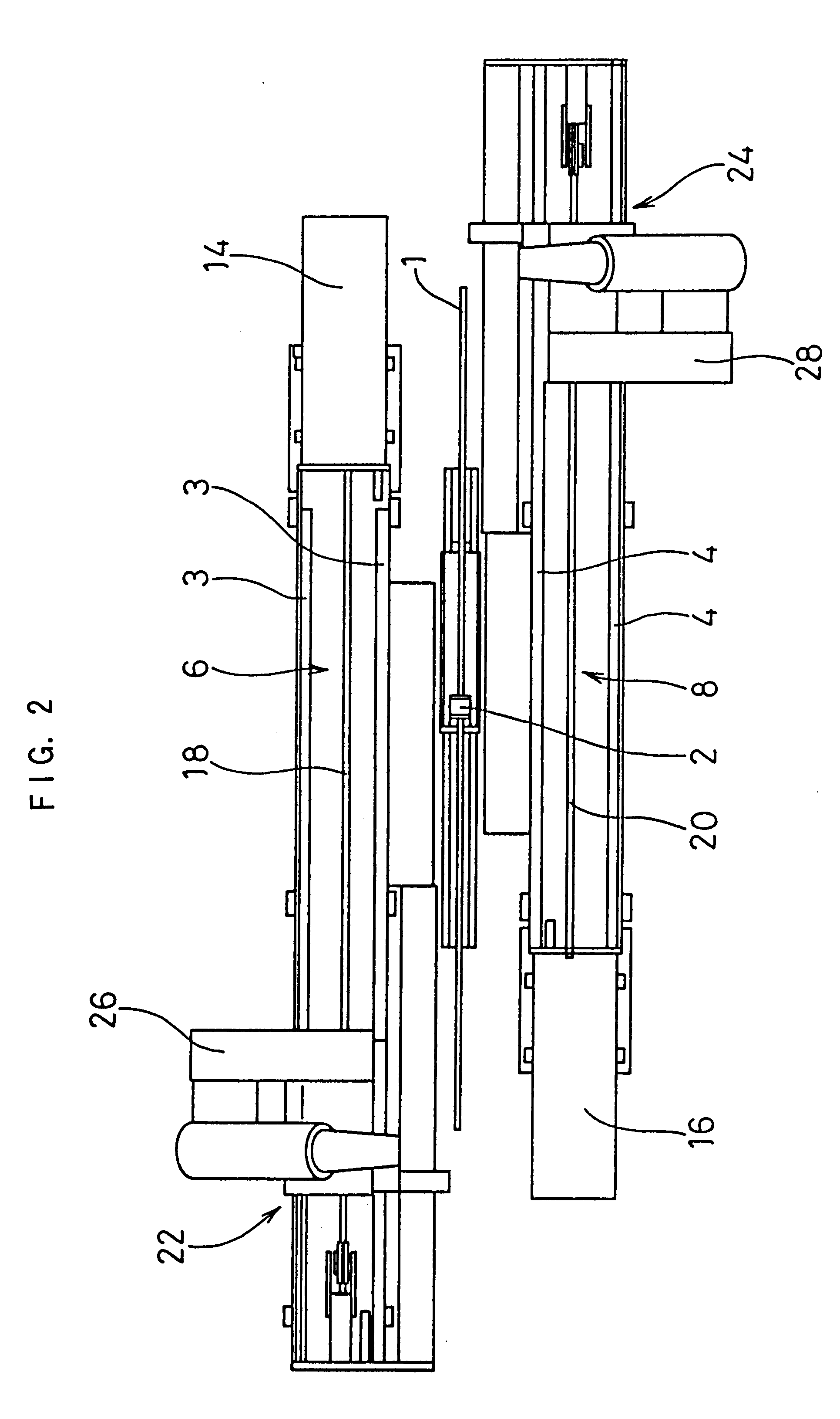
As shown in FIG. 2, tracks 6 and 8 each with two rails 3, 4 laid thereon are arranged in parallel with the work 1 held by the chuck mechanism 2 and on opposite sides of the held work 1. Moving bases 10, 12 are laid on the rails 3, 4 in such a manner that they can move along the rails 3, 4.

The moving bases 10, 12 are moved along the tracks 6, 8 via chains 18, 20 which are rotated by drive mechanisms 14, 16 disposed on ends of the tracks 6, 8, respectively. The moving bases 10, 12, the tracks 6, 8 and the drive mechanisms 14, 16 form first and second moving mechanisms 22, 24.

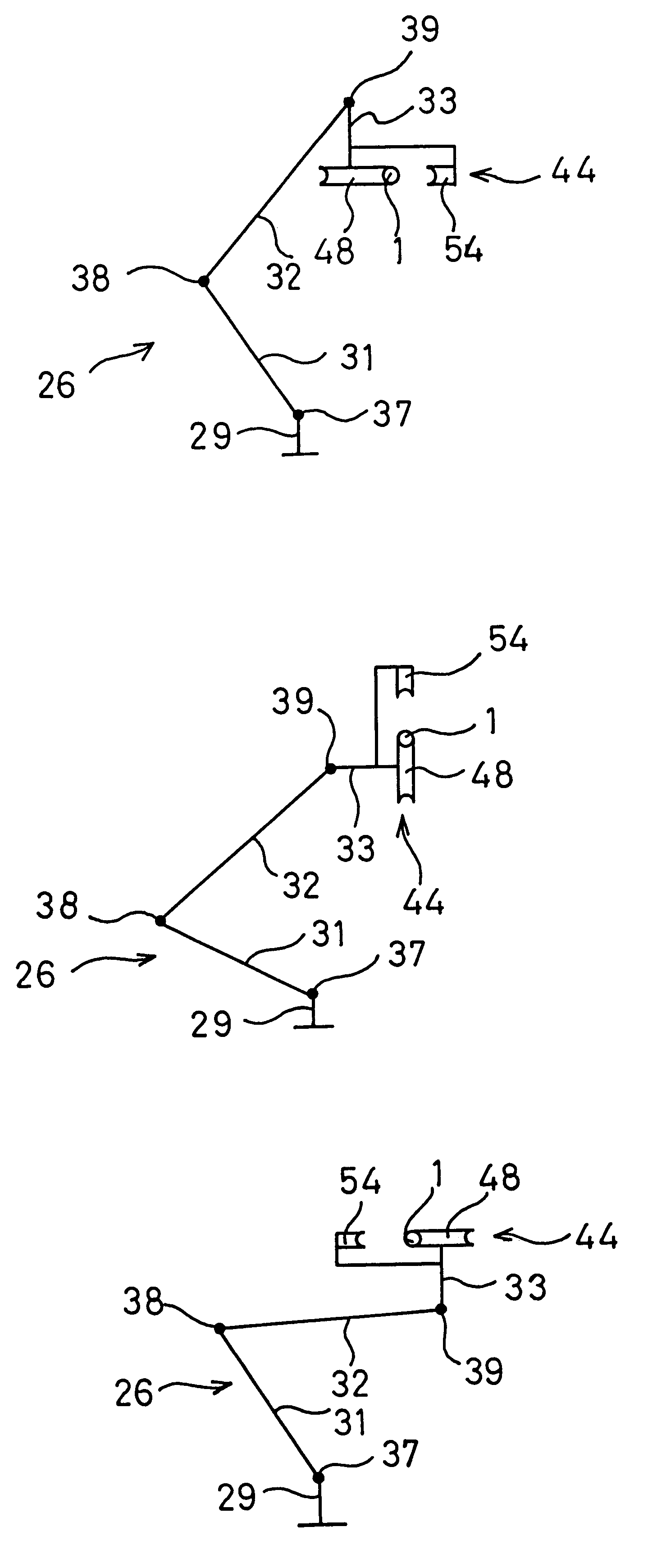
First and second joint type robots 26, 28 are mounted on the movin...


PUM

PropertyMeasurementUnit
Pressureaaaaaaaaaa
Angleaaaaaaaaaa
Bending strengthaaaaaaaaaa

Abstract

There is disclosed a bending device, in which working data of feeding pitch between bending points, bending direction angle and bending angle is prepared from design data of a work, and a dividing point is determined to share the bending process by first and second joint type robots at one place of a straight line of the work able to be held by a chuck mechanism. After trial working, the working data is corrected. During the working, the first and second joint robots having joints rotatable around axes parallel with the axial direction of the work are moved to the bending position The work is held by a bending die and a clamping die rotatable around the bending die of a bending mechanism attached to the tip end of each joint type robot, and bent/worked by rotating the clamping die. When moving to the next moving position, each joint is rotated to change the attitude of the bending mechanism, and the bending mechanism is moved along the work while the work remains between the bending die and the clamping die. After the bending process is completed, the work is held by the bending mechanism of the second joint type robot, moved in accordance with the angle of the bending mechanism of the first joint type robot in a direction in which the bending mehanism of the first joint type robot is not interfered with, and automatically moved to the unloading position.

Description

1. Field of the InventionThe present invention relates to a bending device and a bending method in which when a pipe, a bar material or another longitudinal work is bent / worked, two bending mechanism are moved to successively bend the work from its apposite ends toward its center.2. Description of the Related ArtAs disclosed in Japanese Patent Publication No. 13011 / 1993, a known conventional bending device is provided with a chuck mechanism for holding a pipe or a longitudinal work substantially by its center, two moving mechanisms which can move toward the center position along two tracks provided parallel on opposite sides of the work held by the chuck mechanism, and joint type robots mounted on the moving mechanisms and each having joints rotating around axes parallel with an axial direction of the work. In the bending device, attached to a tip end of each joint type robot is a bending mechanism in which the work is held by a bending die conformed to a bending shape of the work a...

Claims


Application Information

Patent Timeline
IPC IPC(8): B21D7/00B21D7/12
CPCB21D7/12B21D7/14B21D7/024B21D43/027
Inventor KANAMORI, TAKUYA
Owner OPTON KK
Why Eureka
Try Eureka