Pneumatic control of formation and transport of small volume liquid samples

a technology of liquid sample and pneumatic control, which is applied in the direction of positive displacement liquid engine, laboratory glassware, instruments, etc., can solve the problems of ineffective mechanical seals, inability to accept mechanisms or processes for valving fluid volumes smaller than about a hundred nanoliters, and inability to manufacture mechanical seals. ineffective and impractical, and achieve accurate control of flow rate by this method at bes

Inactive Publication Date: 2001-02-27
APPL BIOSYSTEMS INC
View PDF6 Cites 79 Cited by
  • Summary
  • Abstract
  • Description
  • Claims
  • Application Information

AI Technical Summary

Problems solved by technology

However, at the present time, there is no accepted mechanism or process for valving fluid volumes smaller than about a hundred nanoliters.
At dimensions smaller than the microliter dimension, mechanical seals are both ineffective and impractical to manufacture.
However, there exist environmental conditions that compete with the voltage force for effecting hydrodynamic fluid flow, including those induced by small pressure gradients.
Electroosmotic flow is also sensitive to variations in the ionic composition of the fluid, and on factors such as the temperature, so the control of flow rates by this method is inaccurate at best.
In addition, the electroosmotic flow is sometimes detrimental to the circuit function and suppression of electroosmotic control leaves little external control.
As microfluidic circuits become more complicated, electroosmotic control does not effectively provide for isolation of different parts of the circuit.
As a result, the design of microfluidic circuits controlled by electroosmotic forces is limited to only simple circuit designs.
However, as the surface finish of most materials at micron dimensions ...

Method used


Image

  • Pneumatic control of formation and transport of small volume liquid samples
  • Pneumatic control of formation and transport of small volume liquid samples
  • Pneumatic control of formation and transport of small volume liquid samples

Examples


first embodiment

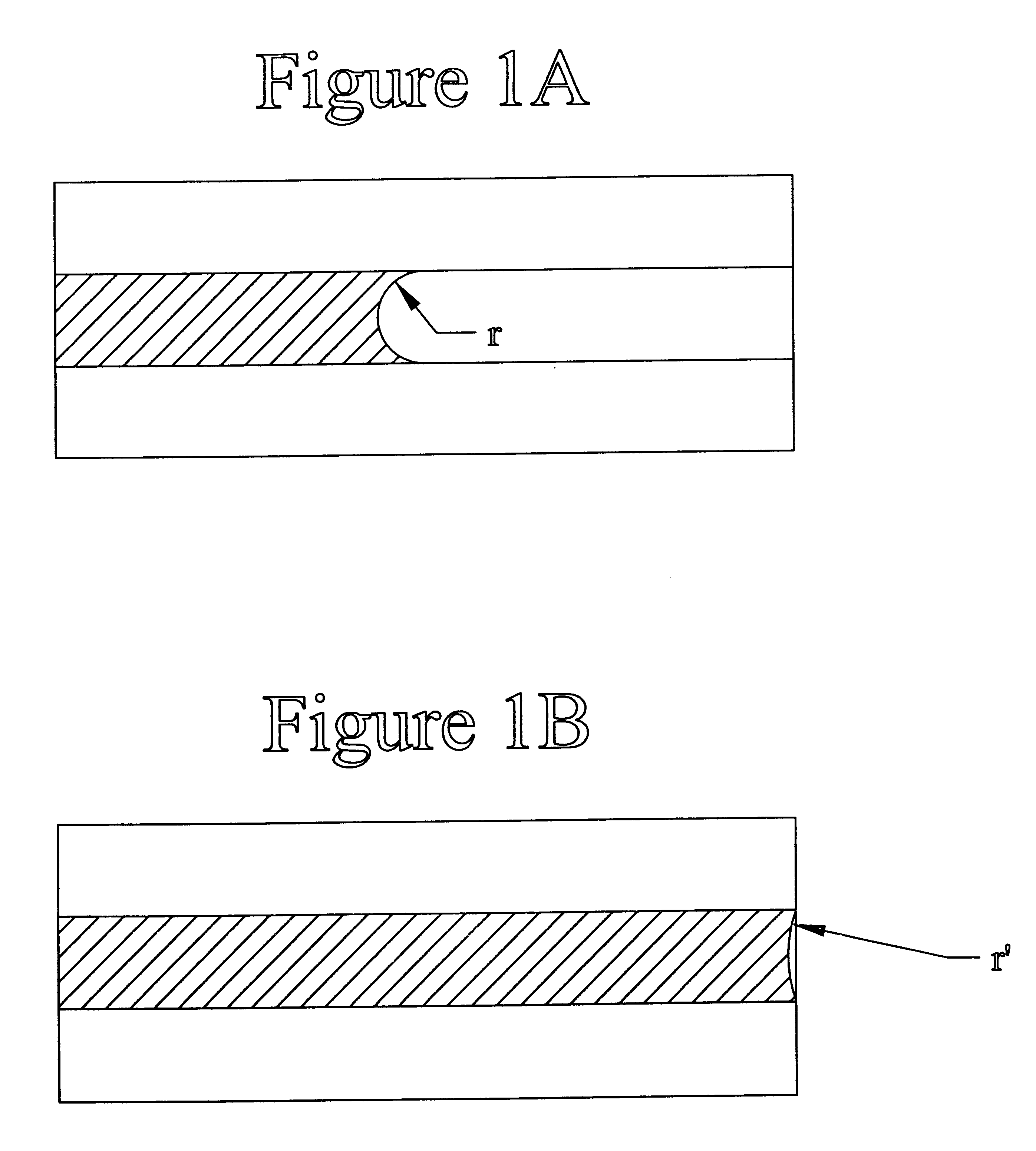
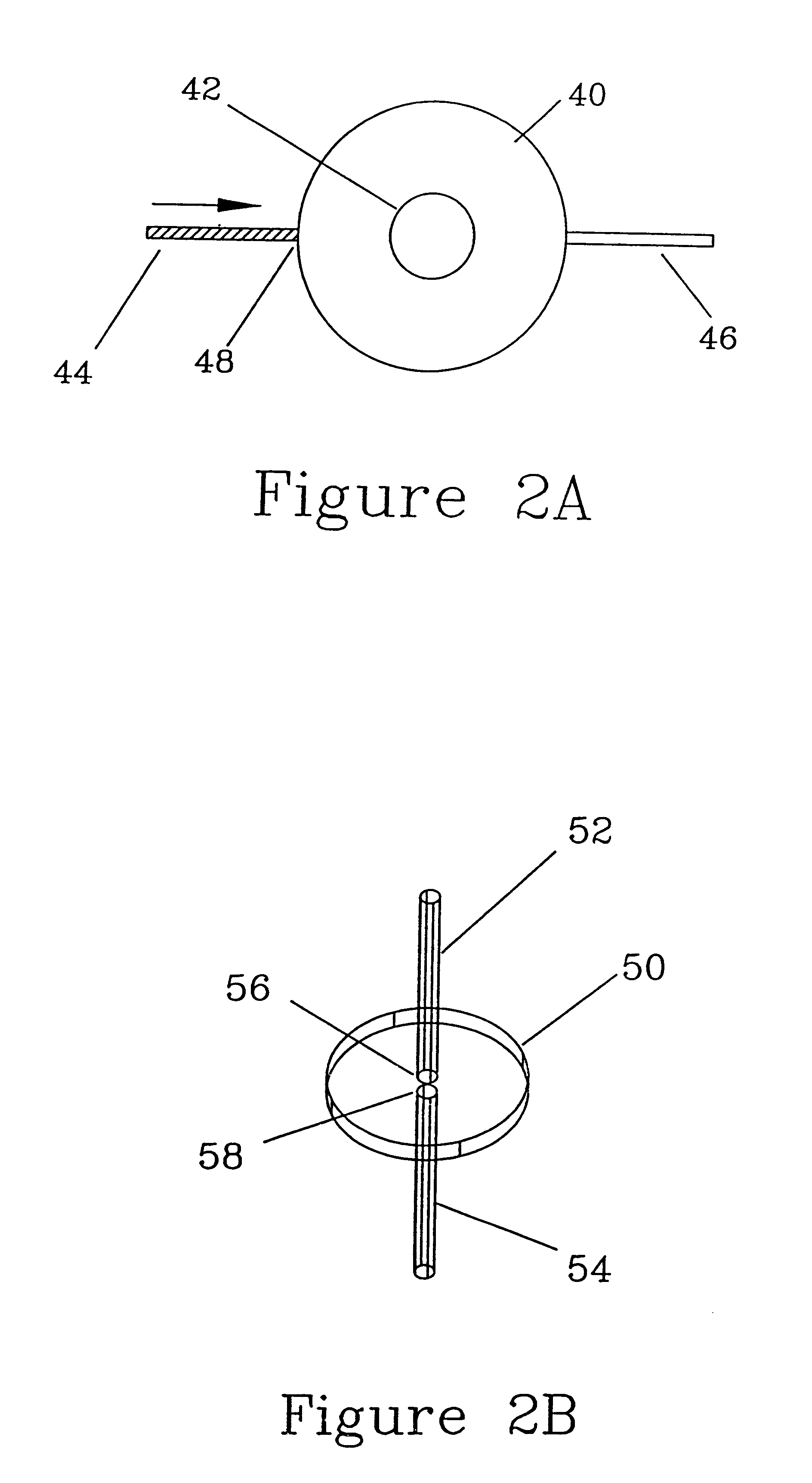
In FIG. 2A, the dimensions of the capillary 44 increase along one axis (normal to the axis of the capillary) at point 48, creating a barrier to motion at that point. By arresting the motion of the meniscus, small volumes can be segregated and defined. Application of a pressure sufficient to overcome the forces holding the meniscus at the gating point permits the flow of the liquid sample to resume, allowing for the delivery of known quantities of liquid to a point of use.

second embodiment

In FIG. 2B, the dimensions of the inlet capillary 52 increase along two orthogonal axes (both normal to the axis of the capillary) to form a cavity 50. A short gap separates the gating point 56 from the mouth 58 of a drain capillary 54. This gap is sufficient to arrest the movement of the meniscus unless the hydrostatic pressure in the capillary 52 is great enough to extrude the liquid into the cavity. This pressure will breach the barrier at the gating point 56 by forming a liquid bridge across the gap. As indicated by the Young-Laplace equation, the barrier to motion of a meniscus across the gap in this embodiment is approximately twice as great as the barrier of FIG. 2A (with capillaries of similar dimensions).

third embodiment

FIG. 2C is a slot 68 cut at right angles through a capillary 62 and 64 to create a gap in the capillary between points 60 and 66. By creating an expansion of the capillary in two dimensions, this gap arrests meniscus movement, but allows the formation of a liquid bridge to a drain capillary 64 when the pressure applied to the volume of liquid in the meniscus is sufficient to overcome the forces maintaining the meniscus at the gate.


PUM


Abstract

A process and system are provided for forming and transporting precise small volumes of liquid samples by means of controlled gas pressures. As the controlled gas pressures are changed at a multiplicity of control points in the fluid circuit, transitions take place involving the transport of small liquid samples. This transport is arrested by the geometry of the fluid circuit to produce a new state, which state remains stable until another transition is initiated by a change in the multiplicity of controlled gas pressures. Various combinations of control elements are described for effecting formation of fixed liquid volumes, transporting, mixing, and removing entrained bubbles from small liquid samples.

Description

(a) Field of the InventionThis invention relates to a process, and system, and to system elements for controlling formation and movement of small volumes of liquid by means of controlled gas pressures. More particularly, this invention relates to a process and system and to system elements for gating, transporting, and mixing small volumes of liquid samples wherein the liquid samples are treated or analyzed.(b) Description of Prior ArtFluid circuits require gates to control fluid movement. However, at the present time, there is no accepted mechanism or process for valving fluid volumes smaller than about a hundred nanoliters. At dimensions smaller than the microliter dimension, mechanical seals are both ineffective and impractical to manufacture.Prior to the present invention, attempts have been made to process small volumes of liquids in the nanoliter range in order to effect a chemical reaction, analysis or the like. For example, capillary microfluidic circuits have been utilized ...

Claims


Application Information

Patent Timeline
IPC IPC(8): B01L3/00B01F11/00B01F13/00G01N1/00B01J4/02G01N35/08
CPCB01F11/0071B01F13/0059B01L3/50273B01L3/502738B01L3/502746B01L2200/0605B01L2200/146B01L2300/0816B01L2300/0864B01L2300/0867B01L2400/0487B01L2400/0688G01N35/1095B01F31/65B01F33/30
Inventor PAUL, CARLTON H.
Owner APPL BIOSYSTEMS INC
Why Eureka
Try Eureka