Card edge connector assembly with ejectors for linear installation/ejection and the associated printed circuit board for use therewith

Inactive Publication Date: 2001-03-20
HON HAI PRECISION IND CO LTD
View PDF3 Cites 15 Cited by
  • Summary
  • Abstract
  • Description
  • Claims
  • Application Information

AI Technical Summary

Problems solved by technology

Moreover, because the contact arrangements of the conventional DIMM connector and of the SO DIMM connector are different from each other, there are still some problems

Method used


Image

  • Card edge connector assembly with ejectors for linear installation/ejection and the associated printed circuit board for use therewith
  • Card edge connector assembly with ejectors for linear installation/ejection and the associated printed circuit board for use therewith
  • Card edge connector assembly with ejectors for linear installation/ejection and the associated printed circuit board for use therewith

Examples


Embodiment Construction

References will now be in detail to the preferred embodiments of the invention. While the present invention has been described in with reference to the specific embodiments, the description is illustrative of the invention and is not to be construed as limiting the invention. Various modifications to the present invention can be made to the preferred embodiments by those skilled in the art without departing from the true spirit and scope of the invention as defined by appended claims.

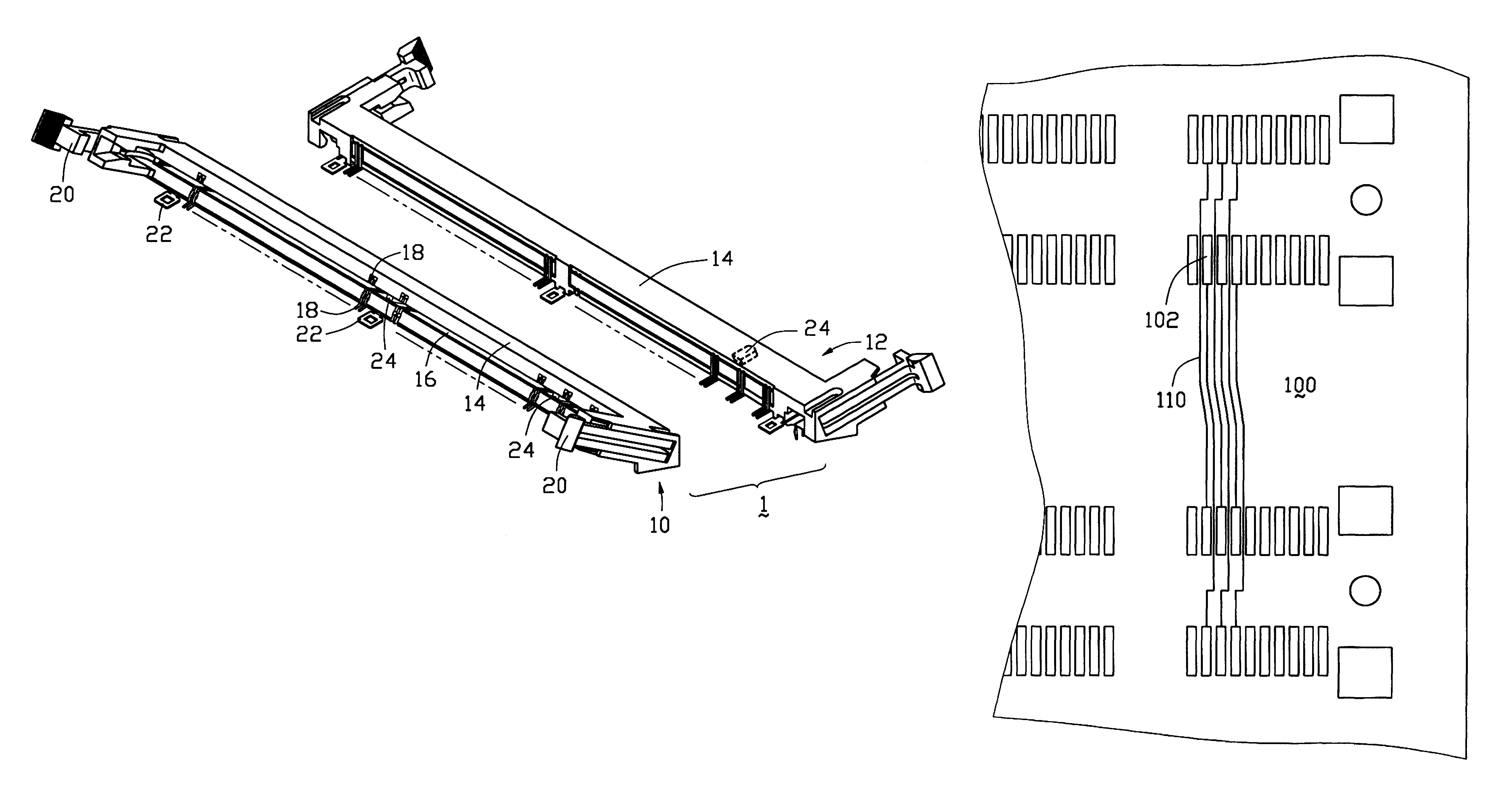
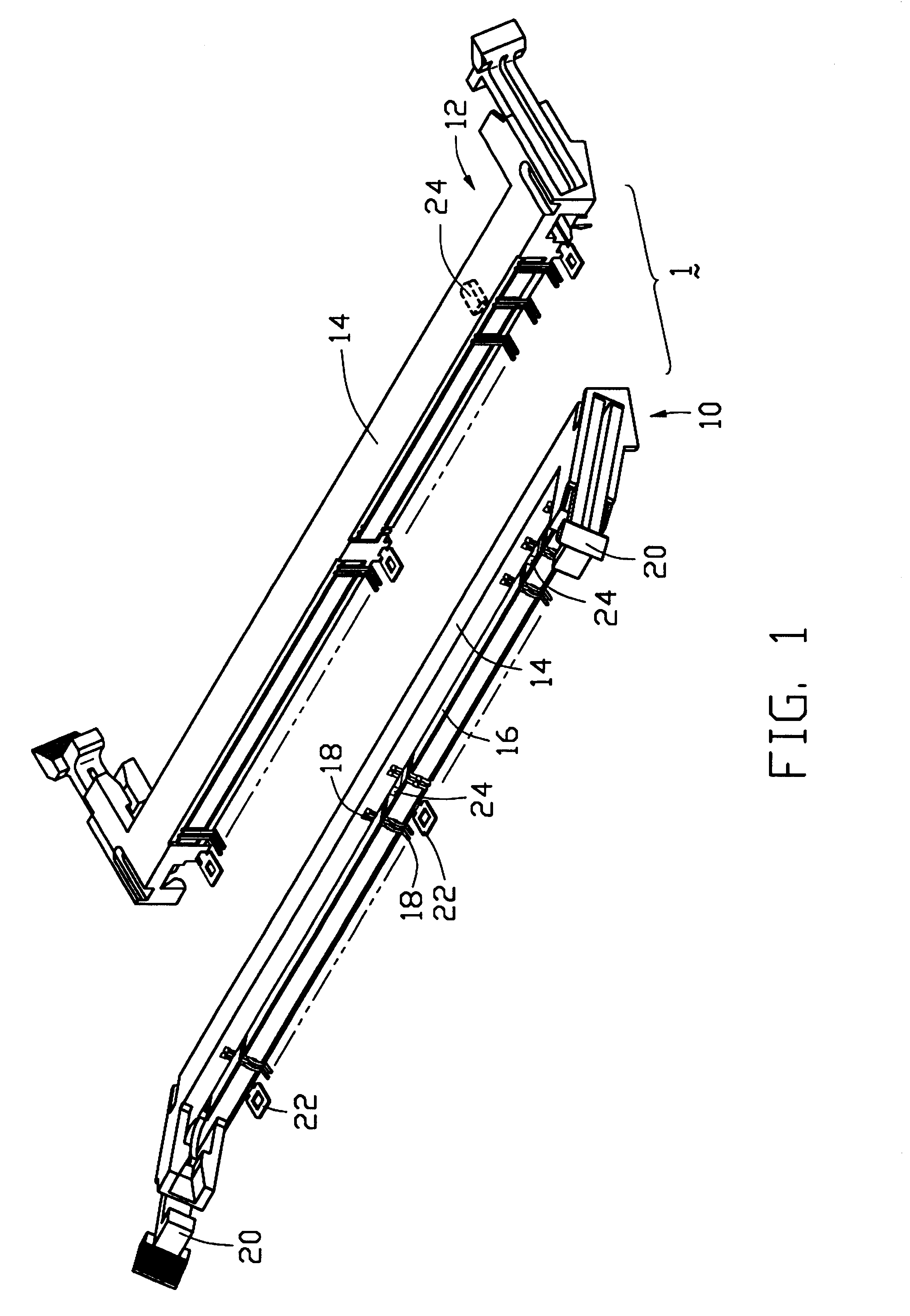
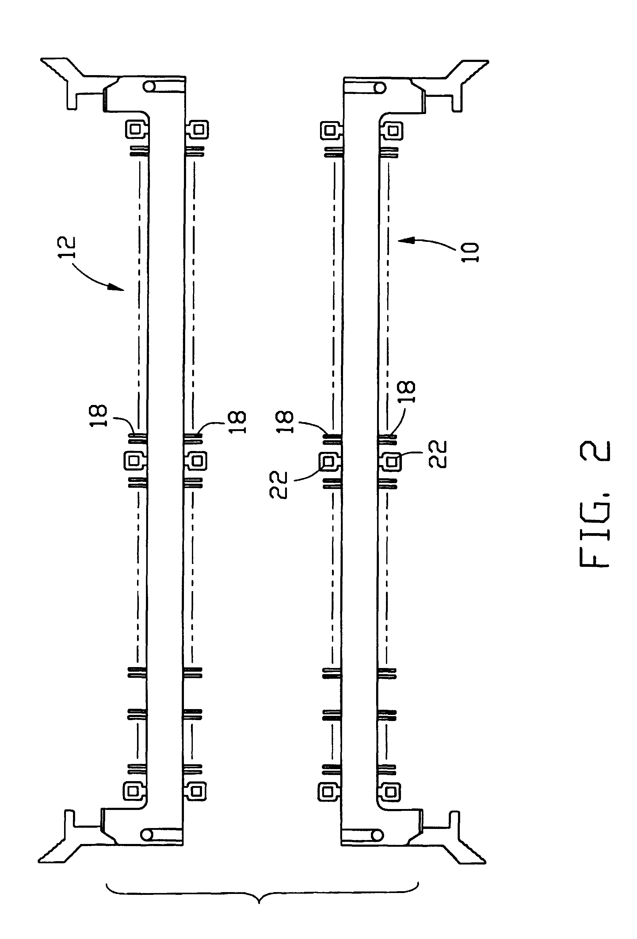
It will be noted here that for a better understanding, most of like components are designated by like reference numerals throughout the various figures in the embodiments. Attention is directed to FIGS. 1-3 wherein a connector assembly 1 includes a first slanted connector 10 and a second slanted connector 12 head to head positioned with each other. The first connector 10 includes an insulative housing 14 defining a central slot 16 along the lengthwise direction thereof for receiving a card (i.e., memory...


PUM


Abstract

A DIMM connection system includes a pair of non-vertical DIMM first and second connectors (10, 12) head to head positioned on a printed circuit board (100). Each of the connectors (10, 12) including an insulative housing (14) defining a central slots (16) for receiving the card therein. Two rows of pairs of contacts (18) are positioned within the housing (14) by two sides of the central slot (16) for engagement with the card. A pair of ejectors (20) are disposed at two opposite ends of the housing (14) for ejecting the inserted card. The key (24) in the slot of the first connector (10) is aligned with that of the second connector (12) in a transverse direction. The pair of contacts (18) of the first connector (10) are aligned with the corresponding pair of contacts (18) of the second connector (12) in the same transverse direction. A printed circuit board (100) is positioned under the pair of connectors (10, 12), and includes four rows of conductive pads (102) thereon corresponding to the contacts (18) of the first and the second connectors (10, 12) wherein for each set including four conductive pads (102) respectively in the four rows and aligned with one another in the same transverse direction, the first conductive pad (102) is electrically connected to the third conductive pad (102) while the second conductive pad (102) is electrically connected to the fourth conductive pad (102) so that both the connectors (10, 12) share the same circuits on the printed circuit board (100).

Description

BACKGROUND OF THE INVENTION1. Field of the InventionThe invention relates to the card edge connector assembly with ejectors to linearly install / eject the card thereinto / therefrom, and particularly to the interconnection system including at least a pair of opposite such card edge connectors in a head-to-head manner with a printed circuit board thereunder.2. The Related ArtThe copending parent application Ser. No. 09 / 016,144 filed Jan. 30, 1998, discloses a slanted conventional DIMM (Dual In-line Memory Module) type card edge connector with ejectors thereon for use with a card or memory module. Another copending parent application Ser. No. 09 / 270,380 filed Mar. 16, 1999, discloses a pair of so-called SO DIMM (Small Out-line Dual In-line Memory Modules) connectors arranged in a head-to-head manner.Anyhow, the SO DIMM connector are generally used in the notebook computers, and the desktop computers still require the conventional DIMM connectors for use therewith due to the corresponding...

Claims


Application Information

Patent Timeline
IPC IPC(8): H01R12/00
CPCH01R12/721H01R12/724H01R12/83
Inventor CHOY, EDMOND
Owner HON HAI PRECISION IND CO LTD
Why Eureka
Try Eureka