
Spintronic magnetic nanoparticle sensors with an active area located on a magnetic domain wall

a magnetic nanoparticle and active area technology, applied in the direction of magnetic field magnitude/direction, measurement devices, instruments, etc., can solve the problems of inability to count large numbers, inability to use suitable amplification methods, and high biological sensitivity, so as to achieve low detection limits, effective detection and counting, and high predictability of the transition

Inactive Publication Date: 2011-02-17
POLITECNICO DI MILANO
View PDF4 Cites 18 Cited by
  • Summary
  • Abstract
  • Description
  • Claims
  • Application Information

AI Technical Summary

Benefits of technology

The invention is a sensor that can detect the presence of magnetic nanoparticles using a special nanostructure that has a unique property called anisotropic magnetoresistance (AMR). The sensor can be made into an array for detecting multiple magnetic nanoparticles, allowing for quantitative measurement of molecular concentrations in biological samples with very low detection limits. The sensor works by measuring changes in the external field required to modify the magnetization configuration of the nanostructure, caused by the proximity of magnetic nanoparticles. The detection of a single molecule with a small nanoparticle can also be achieved.

Problems solved by technology

The magnetic properties of the nanoparticles are stable over the time, since the magnetism is neither affected by the chemistry of the reagents, nor subject to photobleaching (a problem related to the use of fluorescent markers).
In other applications (such as proteomics), however, there are no suitable methods for amplification, therefore a high biological sensitivity is required.
Sensors, designed for detecting individual particles, are not able to count large numbers of molecules, so their application in analyte concentration measurements becomes troublesome.

Method used


Image

  • Spintronic magnetic nanoparticle sensors with an active area located on a magnetic domain wall
  • Spintronic magnetic nanoparticle sensors with an active area located on a magnetic domain wall
  • Spintronic magnetic nanoparticle sensors with an active area located on a magnetic domain wall

Examples


Embodiment Construction

[0031]The devices and the methods described in the scope of the present invention relate to nanostructures. Typically, the nanostructures are structures having at least two dimensions smaller than 1 μm (for example nanometric dimensions). Even though the exact boundaries of the nanostructure class cannot, actually, be defined by a particular numerical dimension value, such a class is however clearly recognizable by those skilled in the art.

[0032]The present invention relates to a sensor for detecting single magnetic nanoparticles and a sensor array for detecting a plurality of magnetic nanoparticles. As it will be more clear from the hereinafter description, the described sensor can be employed to perform single molecule detection and / or employed in systems for synthesis at a single molecule level and / or analysis at a single molecule level. The sensor array is employed for detecting the concentration of target molecules, to which magnetic nanoparticles are linked, as markers.

[0033]T...


PUM


Abstract

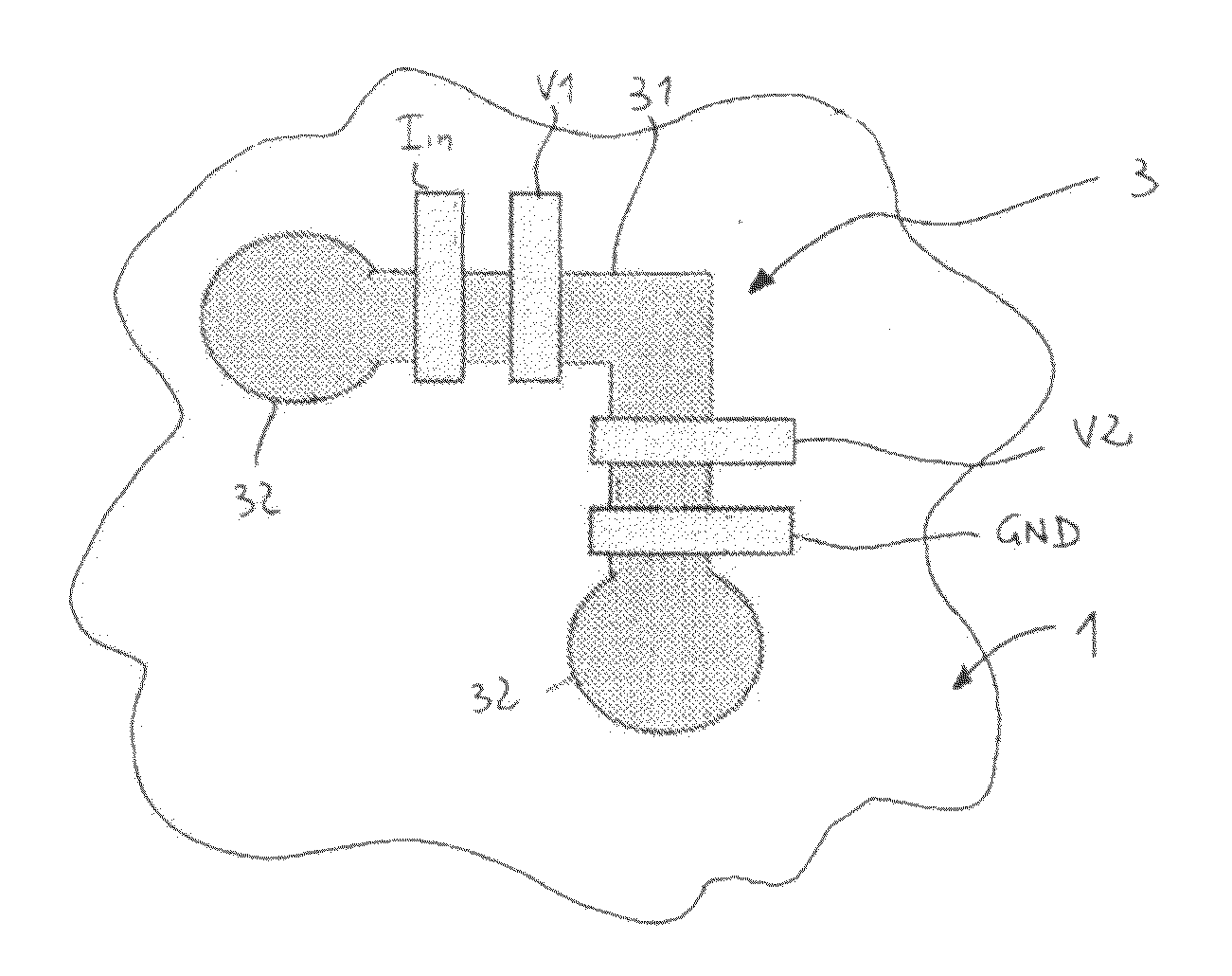
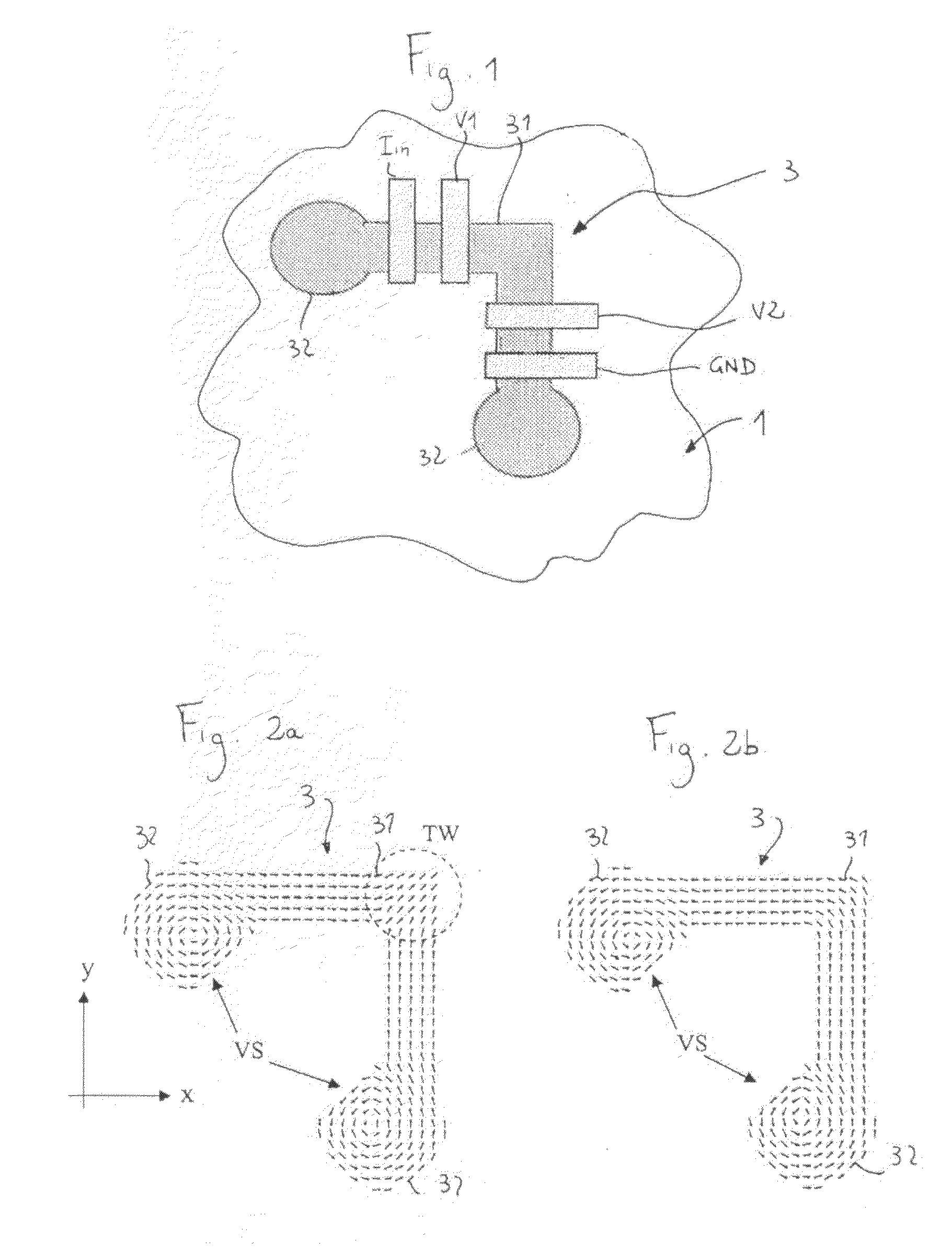
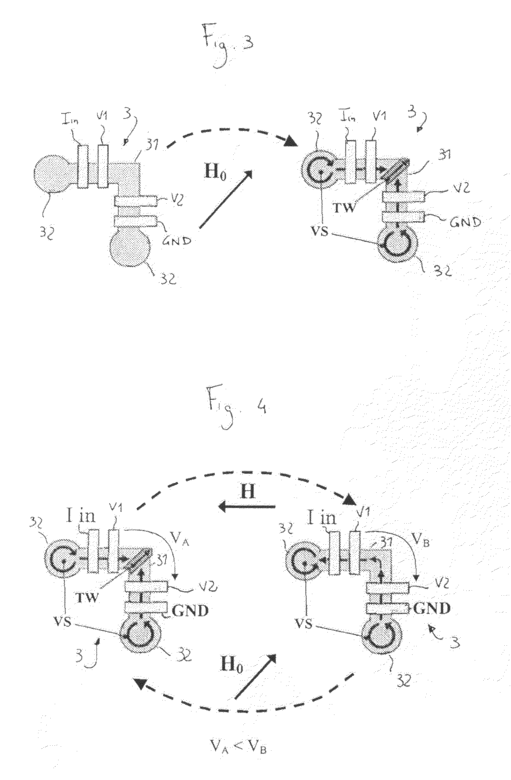
A sensor is described for detecting the presence of a magnetic nanoparticle (N). The sensor is arranged on a support (1), on which a plurality of non-magnetic contacts (Iin, GND, V1, V2) electrically conductively connected to the sensor is disposed. The contacts are adapted to be connected to means for measuring magnetoresistance. The sensor includes a planar ferromagnetic nanostructure (3), comprising a detection area (31) shaped as a strip bent to form a corner. The detection area is adapted to selectively assume, as a response to an applied magnetic field, a first spin configuration comprising a transverse “head-to-head” domain wall (TW), and a second spin configuration, wherein such domain wall (TW) is absent. The transition from the first configuration to the second configuration is affected by the proximity of a magnetic nanoparticle (N) to the detection area.

Description

BACKGROUND[0001]1. Technical Field[0002]The present invention generally refers to magnetic nanoparticle sensors and to molecular recognition procedures, suitable for applications in several different fields.[0003]As such, the biomolecular recognition is the interaction between biomolecules, which have a mutual affinity or present some sort of complementarity. Examples of such interactions are the DNA-DNA hybridization, the antibody-antigen recognition and the ligand-receptor bond [H. A. Ferreira et al., IEEE Transactions on Magnetics 41, 4140 (2005)].[0004]2. Description of the Related Art[0005]The biomolecular recognition is, actually, omnipresent in life, as it constitutes the way the cell mechanisms work. Evident examples are the genetic code replication, the enzyme generation, protein glycids and nucleic acids fabrication and modification, the intracellular and extracellular transport, the cellular metabolism, to mention some of the most common biological processes. On the other...

Claims


Application Information

Patent Timeline
Patent Type & Authority Applications(United States)
IPC IPC(8): G01R33/02
CPCG01R33/1284G01N33/54346
Inventor BERTACCO, RICCARDOVAVASSORI, PAOLO
Owner POLITECNICO DI MILANO
Learn More