Casing slip joint

a slip joint and casing technology, applied in the direction of screw, hose connection, load-modifying fastener, etc., can solve the problem of weakening of the shear screw, and achieve the effect of facilitating the propagation of such cracks

Inactive Publication Date: 2001-05-01
WEATHERFORDLAMB
View PDF27 Cites 32 Cited by
  • Summary
  • Abstract
  • Description
  • Claims
  • Application Information

AI Technical Summary

Benefits of technology

It is, therefore, an object of at least certain preferred embodiments of the present invention to providen new, useful, unique, efficient, nonobvious casing slip joints and self destructive screws for use therewith.

Problems solved by technology

Such a shear screw will work to hold two pieces of a casing slip joint together while the joint is being run into a wellbore, but, over time, the shear screw will weaken, allowing the casing slip joint pieces to separate.

Method used


Image

  • Casing slip joint
  • Casing slip joint
  • Casing slip joint

Examples


Embodiment Construction

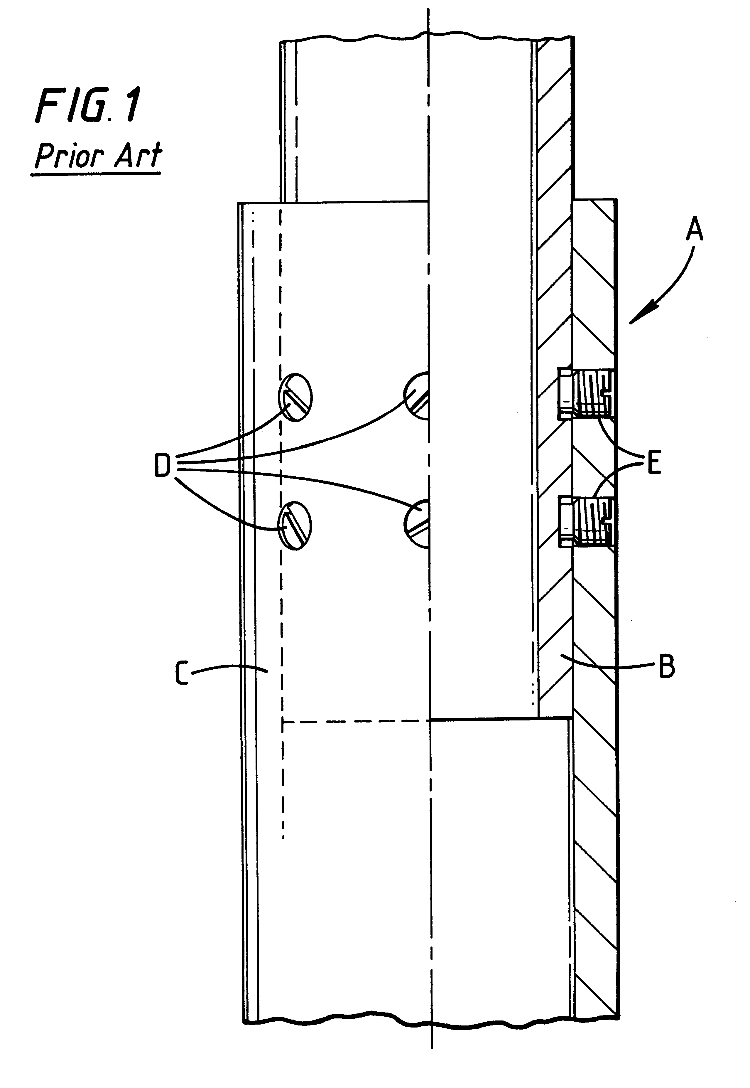
Referring now to FIG. 1, a prior art casing slip joint A has an outer tubular member (e.g. casing) C and an inner tubular member B. Conventional shear screws D in channels E releasably hold the outer tubular member C to the inner tubular member B.

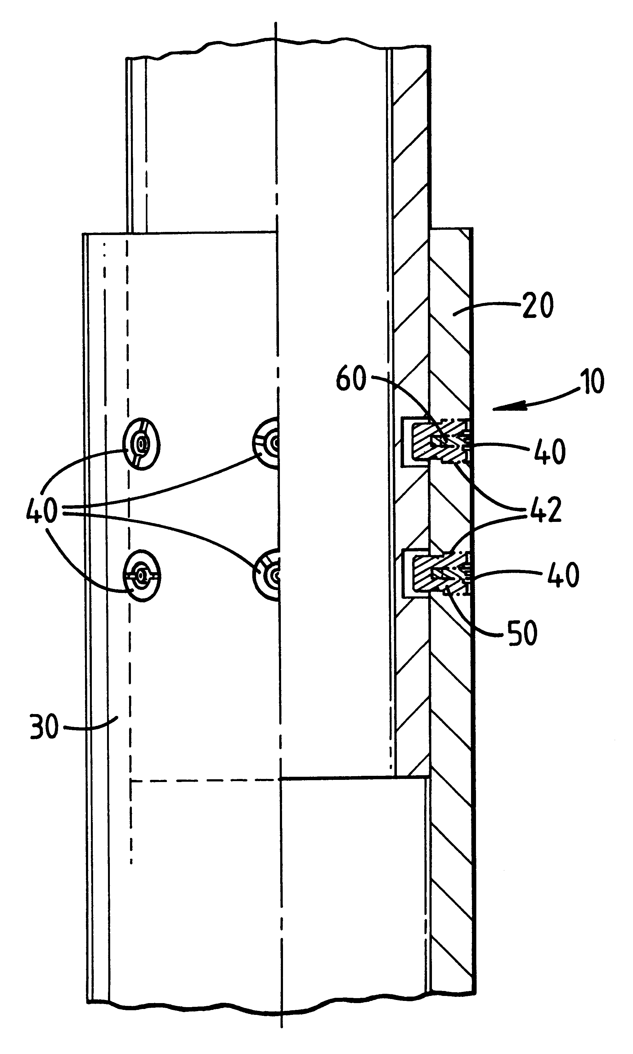
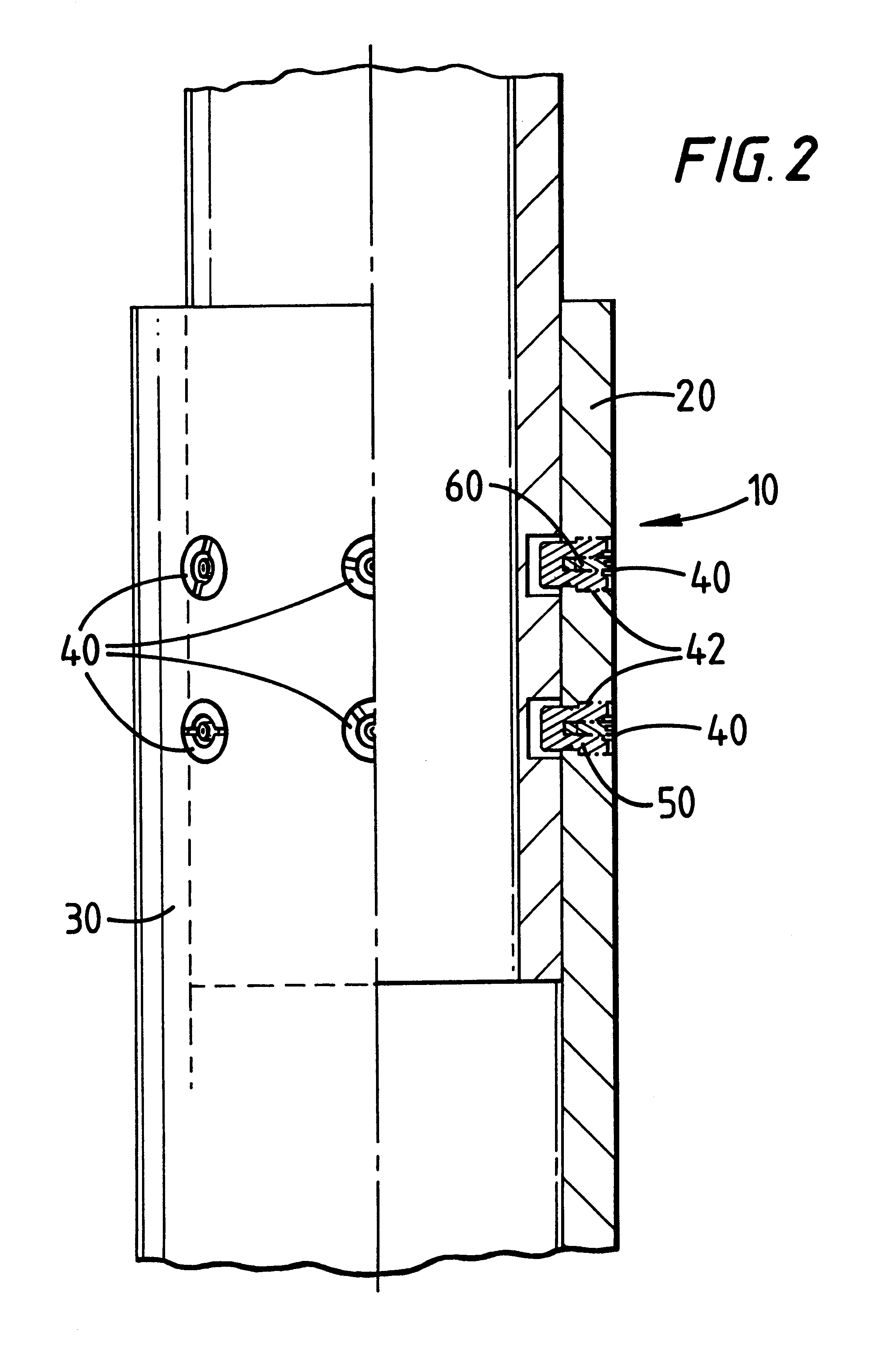
FIG. 2 shows a casing slip joint 10 according to the present invention which has an outer casing 30 (which can be any desired, appropriate length) and an inner casing 20. Self-destructive shear screws 40 in channels 42 through the outer casing 30 releasably attach the two casings together. Each shear screw 40 has an outer shear screw 50 and an inner member 60.

As shown in FIGS. 4A and 4B, the outer shear screw 50 has a body 52 which is generally cylindrical and an internally threaded inner recess 51 for receiving an inner member 60, the recess having a lower end 53. Preferably the shear screws 50 are sufficiently tightened (e.g. about 7 foot pounds) in place so that they are under tension. As shown in FIGS. 4C and 4D, the inner member 60 has...


PUM


Abstract

A casing slip joint has been invented that has a first tubular casing member disposed around and releasably connected to a second casing member, the second casing member within and surrounded by the first casing member. Self-destructive shear screws according to the present invention releasably hold the first casing member to the second casing member. In one aspect, a shear screw according to this invention has an outer shear screw with a central recess and an inner member therein. In one aspect the outer shear screw is made of one metal and the inner screw is made of another so that contact by a well fluid sets up a galvanic cell that produces stress corrosion cracking in the outer shear screw that weakens it and / or destroys it. The propagation of such cracks is facilitated by placing one or more notches or recesses in the body of the components.

Description

1. Field of the InventionThis invention is directed to casing slip joints and to self-destructive fasteners.2. Description of Related ArtThe prior art discloses a variety of casing slip joints that use conventional shear screws or shear fasteners to hold two pieces of a casing slip joint together.SUMMARY OF THE PRESENT INVENTIONThe present invention, in one aspect, discloses a casing slip joint that has a first tubular casing member disposed around and releasably connected to a second casing member, the second casing member within and surrounded by the first casing member. Self-destructive shear screws according to the present invention releasably hold the first casing member to the second casing member. In one aspect, a shear screw according to this invention has an outer shear screw with a central recess. An inner member is introduced into and forcibly held in the central recess of the outer shear screw. The inner member may be an inner screw or bolt that pre-stresses the outer sh...

Claims


Application Information

Patent Timeline
Patent Type & Authority Patents(United States)
IPC IPC(8): E21B17/06E21B17/02E21B17/046
CPCE21B17/046E21B17/06
Inventor ERIKSEN, ERIK P.HAUGEN, DAVID M.MAHMOUD, SALAH
Owner WEATHERFORDLAMB
Why Eureka
Try Eureka