Composite steel structural plastic sandwich plate systems

a composite steel and structural plastic technology, applied in the direction of load accommodation, special-purpose vessels, vessel construction, etc., can solve the problems of increasing the number of framing and supporting elements, reducing the number not eliminating the risk of oil spills. , to achieve the effect of reducing the number of ductility, and reducing the number of framing and supporting elements

Inactive Publication Date: 2006-01-10
INTELLIGENT ENG BAHAMAS
View PDF41 Cites 21 Cited by
  • Summary
  • Abstract
  • Description
  • Claims
  • Application Information

AI Technical Summary

Benefits of technology

[0016]The above-described drawbacks inherent in the art for providing double hull tankers are advantageously eliminated in accordance with the teachings of the present invention by bonding a tough structural elastomer between steel plates to form steel-elastomer-steel composite hull panels, frames and supporting members. The elastomer is preferably hydrophobic to prevent water absorption which could lead to rusting of the plates and should have sufficient ductility to exceed the yield strain of the steel plates without rupturing. The composite panels are used in constructing at least the inner hull of the double hull. Preferably the steel-elastomer-steel composite panels are used to construct the inner hull, outer hull, bulkheads, floors, decks and collapsible frame and support members and may be formed in any necessary shape. The elastomer layer within the composite panels forming the inner hull particularly provides an effective crack arrest layer between the inner steel plate of the inner hull and the outer steel plate of the inner hull, which effectively isolates the inner steel plate of the inner hull from cracks that propagate from the outer hull, the transverse members, such as floor frames and bulkheads, and other supporting elements, such as web frames and horizontal frames, that are designed for both in-service loads and for accidental or extreme loads. Furthermore, because the composite panels are stronger and stiffer than conventional steel plates, the number of framing and supporting elements can be significantly reduced while meeting or exceeding current design standards for strength, service life, construction cost, maintenance cost and survivability. Furthermore, the composite panels may be modified to include voids within the core to lighten the structure or to enhance performance. The shapes, location pattern and orientation of these voids may be optimized to provide the required performance for the particular structure. The voids may be formed with prefabricated rigid foam forms or with forms constructed of light gauge steel or of other materials that are suited to the structure and compatible with the elastomer. Structural shapes or plates may be incorporated to enhance shear stiffness. The connection and shear transfer between these structured shapes and the face plates is in one embodiment provided by bonding the polyurethane elastomer core material to both the structured shape and the face plates without welding. Structural bonding of the face plates or of the faceplates and internal structural shapes or plates may be sufficient to provide adequate shear transfer and eliminate the need for welding between metal parts or surfaces. This attribute is particularly advantageous when dissimilar metals are required to be used for the face plates.

Problems solved by technology

Increased social, economic and political pressure has led to the development of technology to reduce or eliminate the risks of pollution and resulting damage to the marine environment, as well as the loss of valuable cargo, that may result from cargo leaking due to rupture of a vessel under extreme or accidental loads such as collisions, grounding, fire and explosion.
In particular, vessels carrying hazardous materials are increasingly subject to additional requirements imposed by regulatory agencies, ship and cargo insurers, and ship owners and financiers.
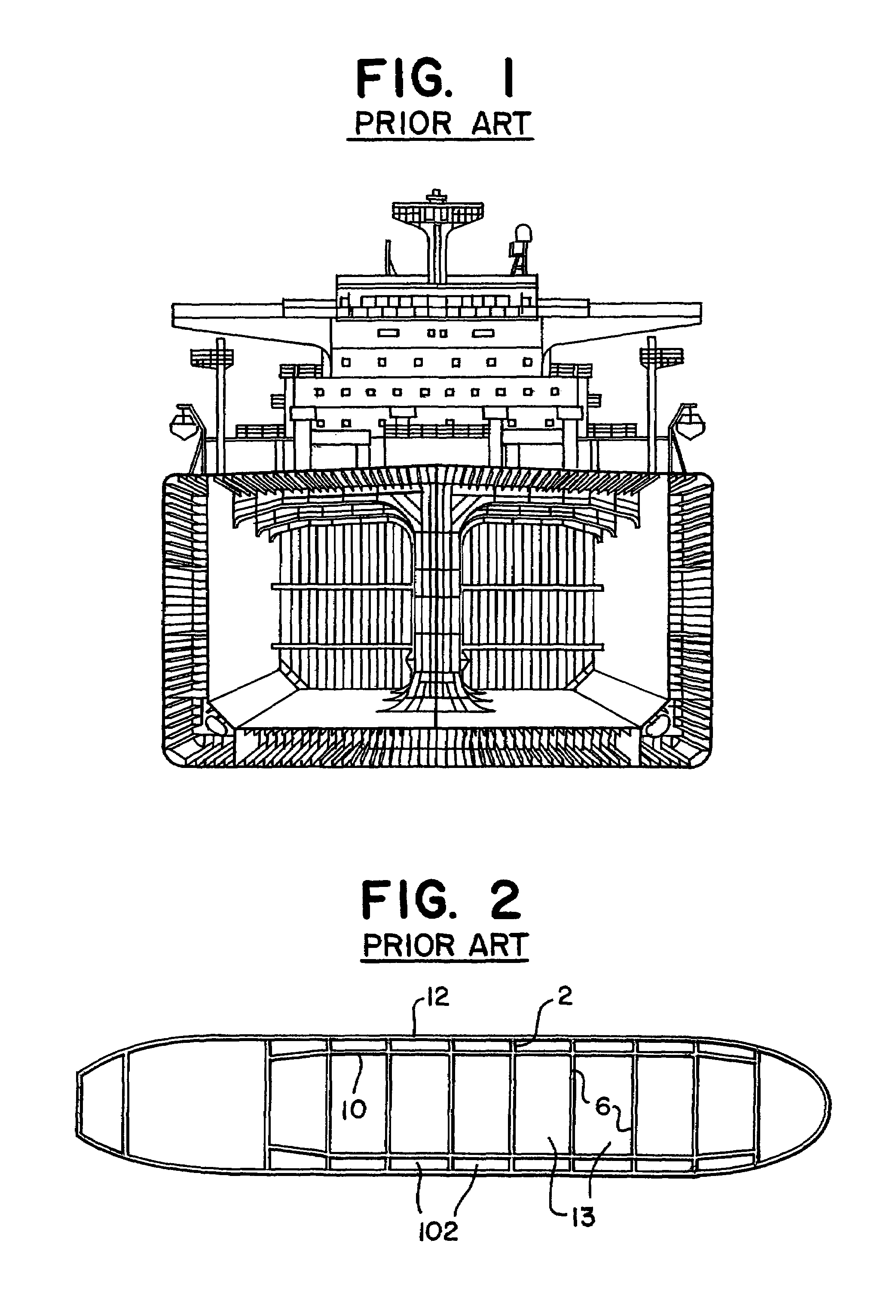
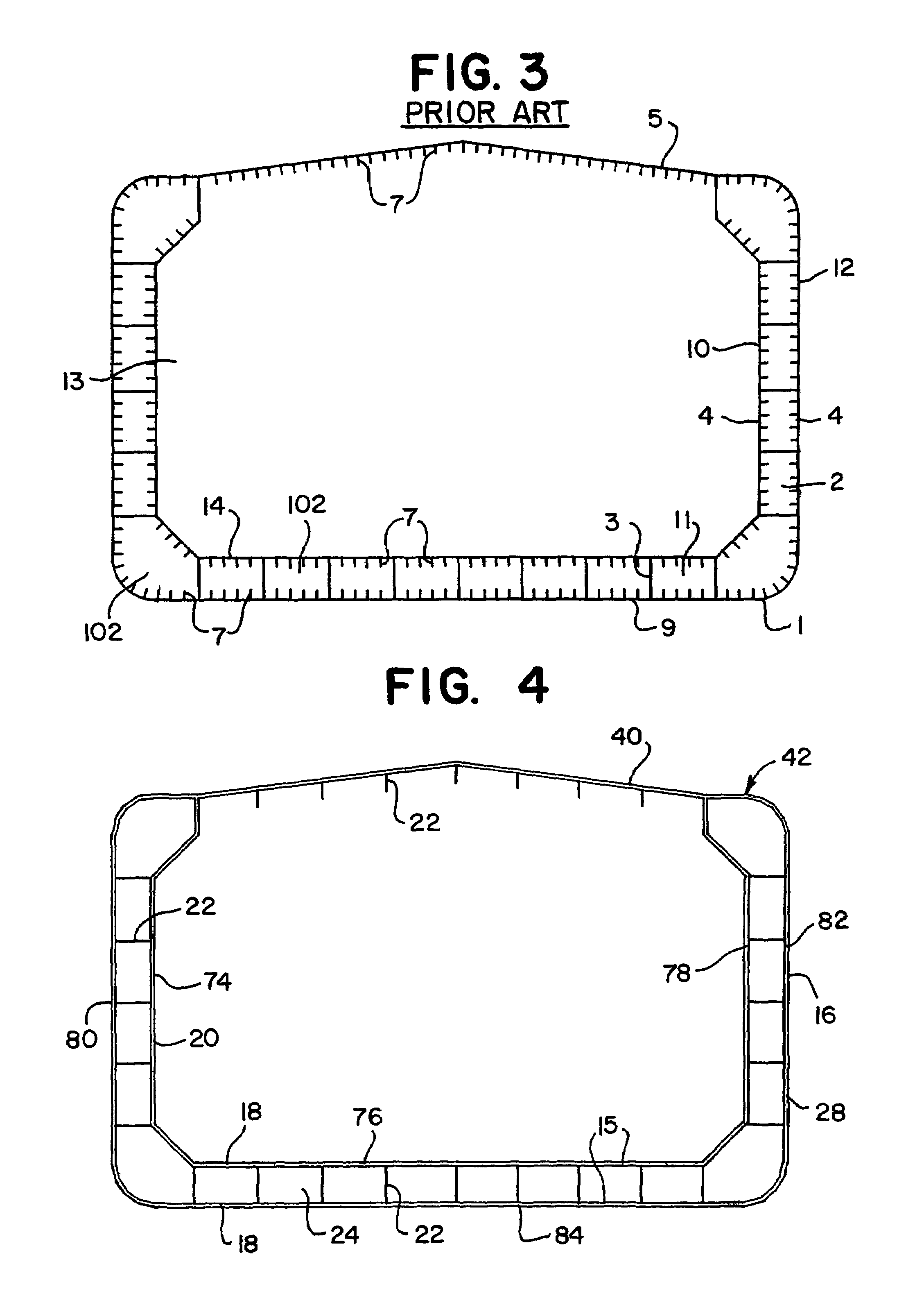
The improved tanker designs, such as double-bottom, double sides, double hull, mid-deck, etc. are known to reduce but not eliminate the risk of oil spills in accidents.
Although tests indicate that an advanced all steel double hull design will dissipate more energy than a conventional all steel double hull design, both designs are subject to compromise of the inner hull due to crack propagation resulting from fatigue cracks or from cracks that propagate from a ruptured plate during extreme load events.
These retrofitted external hull structures fail to address the possibility of crack propagation into the inner hull due to rupture of the outer hull, and inadequately address the cost and practicality of fabrication and maintenance of the auxiliary hull structure.
In current retrofit designs, access between the hulls for inspection and corrosion maintenance is difficult, if not impossible.
The external hull in a retrofit design generally does not participate in carrying all of the operational loads, and adds significant dead weight to the tanker with limited structural functionality.
Current all steel double hull construction has serious disadvantages which lower the likelihood that these design types will meet the performance criteria of zero oil outflow after accidental or extreme load events such as collisions, groundings, explosions or fire, and remain competitive relative to construction, maintenance and service life costs.
One disadvantage is that current double hull construction is based on traditional naval architecture design concepts in conjunction with international agreements and national standards that stipulate the use of double hull construction with a minimum separation between hulls which is related to statistical data of measured rock penetrations from recorded tanker casualties.
This complex hull structure and plate stiffener system is a source of fatigue failures and a source for tearing (rupture) of the hull plate during accidental or extreme loads.
This type of hull is costly to fabricate due to the large number of pieces which must be cut, handled and welded, and because of the significantly increased surface area on which protective coatings must be applied.
Also, these typical complex structural systems are very congested, leading to poor access, poor inspection, poor and costly maintenance, and a decreased service life due to corrosion.
Recent large scale grounding tests on double hull sections also indicate that despite the superiority of double hull vessels over single hull vessels, rupture of the interior hull of currently available steel double hull designs may occur as a result of crack propagation from the initial rupture of the outside hull primarily at or near transverse structural members.
Therefore, preventing or reducing oil outflow in the event of accidental or extreme load events is not adequately addressed by currently available design alternatives.
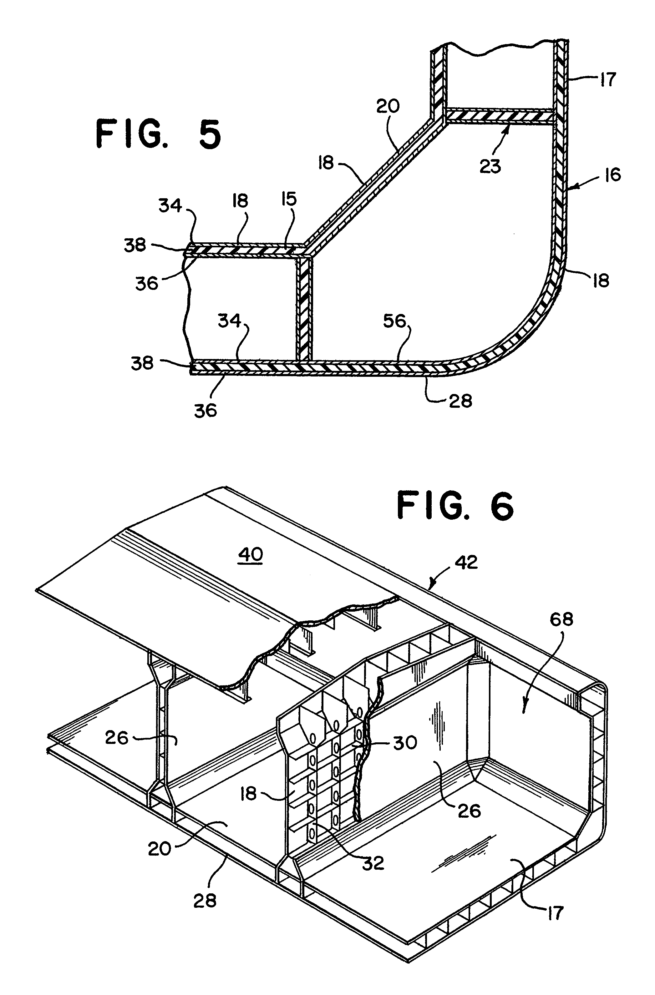
These tests illustrate that polyurethane foam does not adequately adhere to the steel plates and has little shear strength.
The low density foam used in the test composite had little or no tensile strength and insufficient compressive strength to be beneficial structurally.
Therefore, the desired crack arresting structural composite configuration was not achieved.
The tested foam possessed some energy absorption capacity; however, this capacity was small when compared to that of the steel in membrane action.
The foam lessens the localized straining of the steel plates around a concentrated load point which delays, but does not prevent, the shear tension failure of the steel hull plates.
For example, orthotropic steel bridge decks have a reduced fatigue life due to the rupture of the welds that join the deck plate with the stiffening elements.
These welds are subject to cyclic concentrated leads from traffic which cause large localized transverse stresses in the weld as the deck plate bends over the stiffening elements.

Method used


Image

  • Composite steel structural plastic sandwich plate systems
  • Composite steel structural plastic sandwich plate systems
  • Composite steel structural plastic sandwich plate systems

Examples


Embodiment Construction

[0038]The teachings of the present invention are applicable to any structure, vessel, tanker, bulk carrier or ship in which it is desired to contain the contents during an extreme or accidental load event or where it is desirable to enhance fatigue life, improve thermal insulation, improve acoustical insulation, improve dampening characteristics to control vibrations or to connect similar or dissimilar metals without welding.

[0039]The connection of dissimilar metals is especially relevant in storage tanks where vegetable oils, palm oils or other edible oils must be stored without contamination or where corrosive materials must be stored. Generally, metal liners like stainless steel are used as these liners. These speciality metals tend to be substantially more expensive than the support structure. Connecting or welding dissimilar metals involves complicated and costly procedures like explosion bonding, which may not be applicable to or suitable for joining thin plates. Additionally,...


PUM

PropertyMeasurementUnit
thicknessaaaaaaaaaa
tensile strengthaaaaaaaaaa
elongationaaaaaaaaaa

Abstract

A composite structural laminate plate suitable for building maritime vessels or for building civil structures such as double hull oil tankers, bulk carriers, barges decks for roll-on roll-off ferries, orthotropic bridge decks or for building any structural application in which the traditional method of construction uses stiffened steel plates. The laminate has two facing metal layers that are structurally bonded to a polyurethane elastomer core which may have steel or rigid foam void sections embedded within. The laminate provides equivalent in plane and transverse stiffness and strength, reduces fatigue problems, minimizes stress concentrations, improves thermal and acoustical insulation, and provides vibration control. The laminate provides a structural system that acts as a crack arrest layer and that can join two dissimilar metals without welding or without setting up a galvanic cell. For applications like double hull oil tankers, the structural system provides an impact resistant structure that isolates the innermost hull skin from cracks, thereby preventing a loss of cargo such as oil into the environment, when accidental or groundings occur and the outer hull is pierced, penetrated, or ruptured.

Description

CROSS-REFERENCE TO RELATED APPLICATIONS[0001]This is a continuation of U.S. patent application Ser. No. 09 / 496,072, which was filed on Feb. 1, 2000 and issued on Mar. 16, 2004 as U.S. Pat. No. 6,706,406, and which is a continuation-in-part of U.S. patent application Ser. No. 09 / 053,551, which was filed on Apr. 1, 1998 and is now abandoned and which is a continuation of U.S. patent application Ser. No. 08 / 746,539, which was filed on Nov. 13, 1996 and issued on Jul. 14, 1998 as U.S. Pat. No. 5,778,813. U.S. patent application Ser. No. 09 / 854,175 was filed on May 11, 2001 as a divisional of U.S. patent application Ser. No. 09 / 496,072 and issued on Oct. 7, 2003 as U.S. Pat. No. 6,630,249. U.S. patent application Ser. No. 09 / 075,108 was filed on May 8, 1998 as a continuation-in-part of U.S. patent application Ser. No. 08 / 746,539 and issued on Apr. 18, 2000 as U.S. Pat. No. 6,050,208. U.S. patent application Ser. No. 10 / 138,919 was filed on May 3, 2002 as a continuation-in-part of U.S. pa...

Claims


Application Information

Patent Timeline
Patent Type & Authority Patents(United States)
IPC IPC(8): B32B27/40B29C65/00B32B15/04B32B5/14B32B15/06B32B15/08B63B3/14B63B3/20B63B3/68B63B5/00B63B25/08E04C2/292E04C2/34
CPCB32B15/06B32B15/08B63B3/20B63B3/68E04C2/292E04C2/34B63B25/082B63B3/14B63B5/00Y10T428/12562B63B2005/245Y10T428/24967Y10T428/12361Y10T428/12347Y10T428/249958Y10T428/24996Y10T428/24999Y10T428/31551Y10T428/31605Y10T428/31678Y10T428/31681
Inventor KENNEDY, STEPHEN J.
Owner INTELLIGENT ENG BAHAMAS
Why Eureka
Try Eureka