
Artificial foliage

a technology of artificial foliage and stems, applied in the field of artificial foliage assembly, can solve the problems of meeting the user's needs, time-consuming and tedious manual straightening and/or rebending of stem and leaf portions of the structure, etc., and achieves the effect of sufficient ductility and elasticity, minimal effort, and sufficient degree of elasticity

Active Publication Date: 2006-01-12
AMERICAN PRIDE OUTDOORS LLC
View PDF3 Cites 4 Cited by
  • Summary
  • Abstract
  • Description
  • Claims
  • Application Information

AI Technical Summary

Benefits of technology

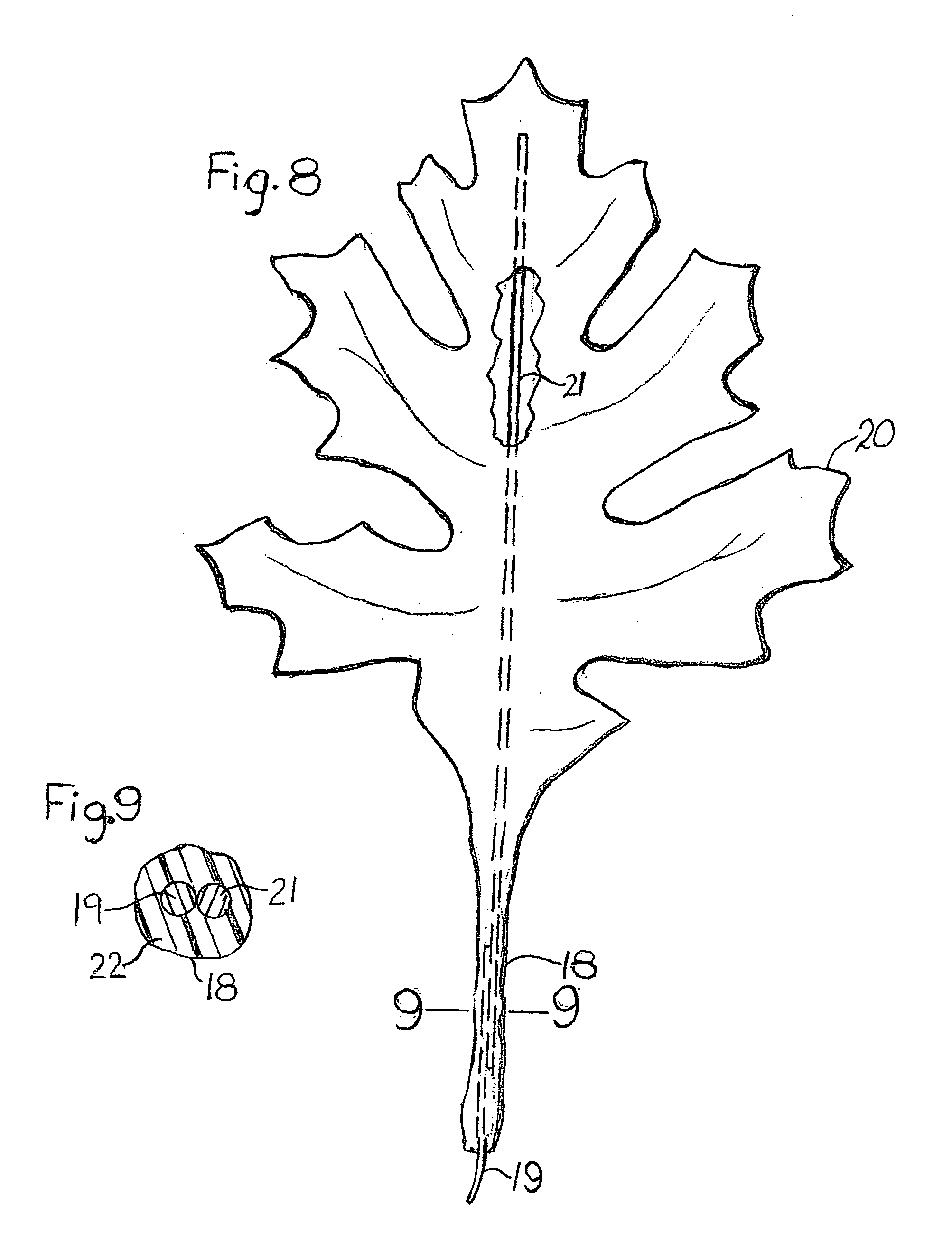
[0008] Another object is to provide a simulated plastic leaf molded about a springy wire segment which extends generally along its centerline. Such wire segment will have a sufficient degree of elasticity to cause it and the leaf to spring back to its original shape and orientation when a deflecting load is removed.
[0009] Yet another object is to provide artificial foliage components molded about plural-part cores made up of wire segments having differing resistances to bending and differing elasticities. Thus, the wires encased in large limbs and major branches projecting therefrom are characterized by sufficient ductility and elasticity to allow the user to shape and orient them by giving them a set quickly and with minimal effort. On the other hand, those supporting cores molded inside small branchlets and leaves attached thereto are more lightly constructed, i.e. of smaller diameter, but are made of metal having greater hardness, stiffness and elasticity than do the softer core wires imbedded in the larger, heavier limbs and branches. The principal advantage provided by such differing characteristics of the various core wires is that the cores of the branchlets and myriad leaves of a foliar structure can avoid plastic deformation as the structure is collapsed and, at the same time, store sufficient elastic energy to cause the branchlets and leaves to return to their previous shapes and orientations with little or no user assistance.

Problems solved by technology

Such compaction of the relatively inelastic wire cores of the stem and leaf portions of the wire framework causes them to take on a set condition which will not likely meet the user's needs upon subsequent redeployment of the structure.
Therefore, time-consuming and tedious manual straightening and / or rebending of stem and leaf portions of the structure can be expected.

Method used


Image

  • Artificial foliage
  • Artificial foliage
  • Artificial foliage

Examples


Embodiment Construction

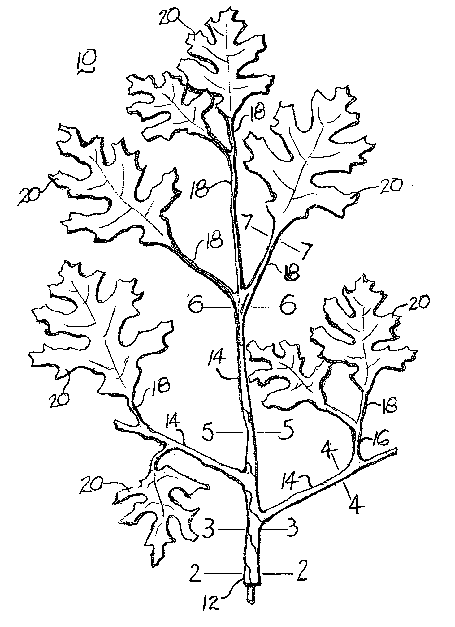
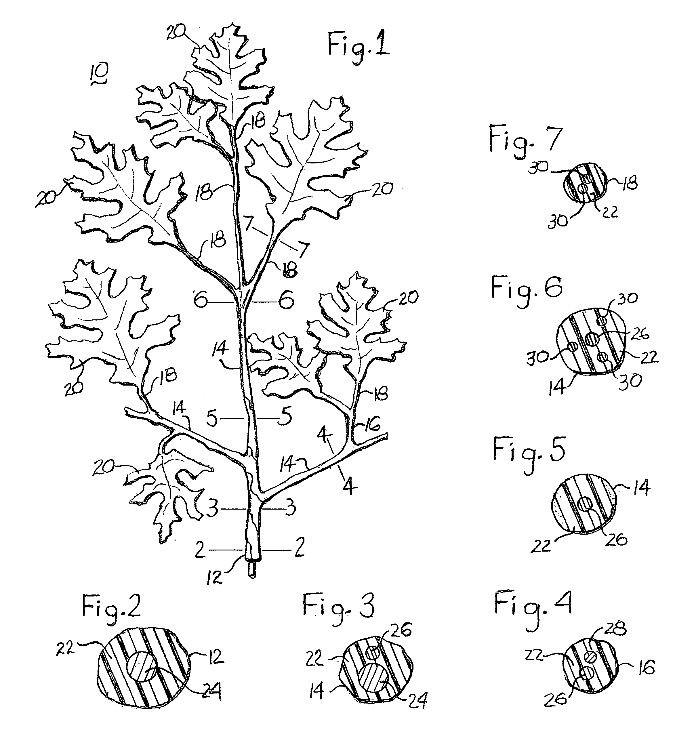
[0021] An artificial foliage structure, designated in its entirety by numeral 10 in FIG. 1 of the drawings, may be fabricated using a previously known method whereby overlapping end segments of metallic wires are laid side by side in an elongated cavity of an injection mold of suitable size and shape. After the cavity is filled with plastic material which is allowed to harden, the wire segments will be held in position within a resulting semi-rigid casing. As will be fully described hereinafter, the individual wire segments comprise a composite interior framework for the foliage structure which secures the constituent foliar parts together, more or less as shown in FIG. 1, while permitting a degree of flexibility of the individual parts.

[0022]FIG. 1 is illustrative of one of the many different foliar structures that can be fabricated using the molding method suggested above. Commonly, such structures include a central limb 12 which supports laterally extending main branches 14 that...


PUM


Abstract

An artificial foliage structure with wire cores embedded in its leafy parts causing these parts to “spring back” upon removal of compressive loading acting thereupon. These wire cores may be made of hard, springy steel such as piano wire or small diameter spring wire. Thicker, woody limbs and branches have embedded therein heavier wire cores that are sufficiently soft to be given a set solely by manually applied bending force.

Description

BACKGROUND OF THE INVENTION [0001] This invention relates to a naturally appearing artificial foliage assembly comprising limbs, branches, stems and leaves. The foliar elements disclosed herein represent certain improvements over those of the arborescent concealment artifice previously disclosed in U.S. Pat. No. 6,306,491 issued to D. B. Pitman, the present inventor. [0002] Pitman assembles artificial foliar components such as limbs, branches, stems and leaves by means of a unitarily molded plastic encasement or sheath. According to Pitman, his components have discrete reinforcing wire core portions which are joined by molding his plastic sheath thereabout. Pitman envisions a life-like foliar structure which a user can draw in about himself by plastically bending the skeletal wire framework carrying his foliar components. To facilitate ready bending of the framework for concealment and for reverse bending to a restored condition, Pitman suggests these characteristics and properties ...

Claims


Application Information

Patent Timeline
Patent Type & Authority Applications(United States)
IPC IPC(8): A01N3/00
CPCA41G1/00Y10S428/919Y10S135/901
Inventor PITMAN, DAVID B.
Owner AMERICAN PRIDE OUTDOORS LLC
Learn More