
Metallic flat product which is subjected to surface finishing by hot-dip coating and which is preferably composed of steel

a flat product and hot-dip coating technology, applied in the direction of superimposed coating process, coating, transportation and packaging, etc., can solve the problems of increased time and cost, reduced ductility, and relatively thick alloy layer formation, etc., to achieve excellent anti-corrosion protection, reduce weight, and reduce the effect of ductility

Inactive Publication Date: 2018-09-25
THYSSENKRUPP STEEL EURO AG
View PDF10 Cites 3 Cited by
  • Summary
  • Abstract
  • Description
  • Claims
  • Application Information

AI Technical Summary

Benefits of technology

The present invention is about improving the coating of metallic flat products to make them more flexible and resistant to corrosion. One way to achieve this is by using a metal melt containing zinc and magnesium. The surface layer is made from a metal melt with a lower content of aluminum and magnesium. This results in better ductility and noise deadening characteristics. To ensure a strong connection between the different layers, a continuous transition region is used, which is at least 2 μm thick. This region is formed through a hot-dip coating process. The technical effects of this invention are improved flexibility, better corrosion resistance, and reduced noise from the metal flat product.

Problems solved by technology

The anti-corrosion protection realized by means of this coating is however not as good as that realized in the case of a pure aluminum coating (FAL type 2).
Owing to the absence of silicon in the melt, however, a relatively thick brittle alloy layer forms, which exhibits a tendency for crack formation and for peeling of the metal coating, during the deformation of the coated flat product.
These measures are however associated with additional expenditure of time and costs.
Furthermore, the production characteristics may be impaired by oxide formation, for example between the working steps, or by microstructural changes resulting from the heat treatment.

Method used


Image

  • Metallic flat product which is subjected to surface finishing by hot-dip coating and which is preferably composed of steel
  • Metallic flat product which is subjected to surface finishing by hot-dip coating and which is preferably composed of steel
  • Metallic flat product which is subjected to surface finishing by hot-dip coating and which is preferably composed of steel

Examples


Embodiment Construction

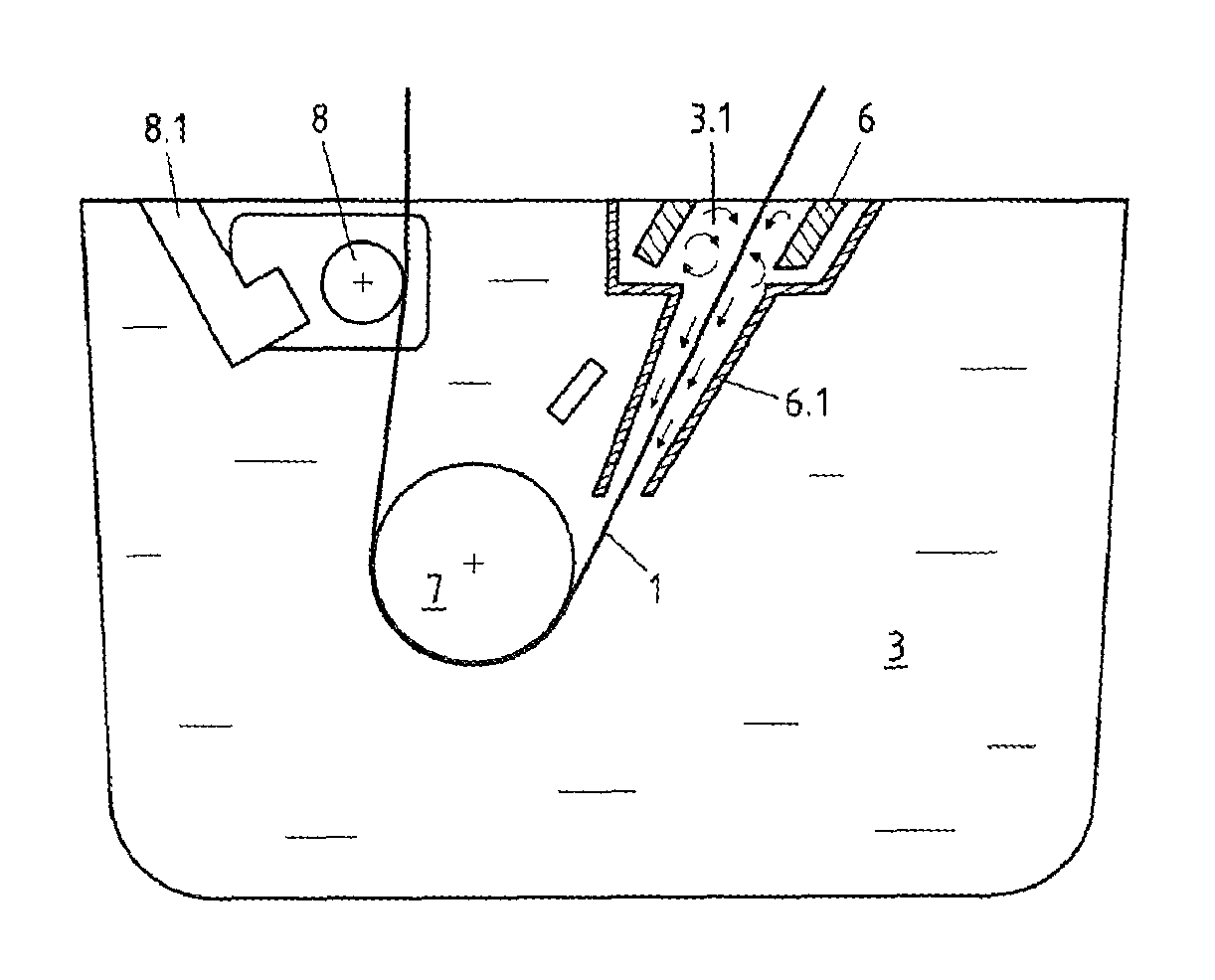
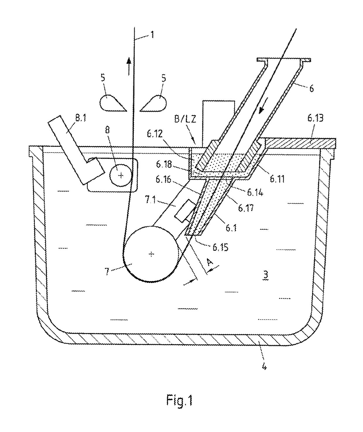
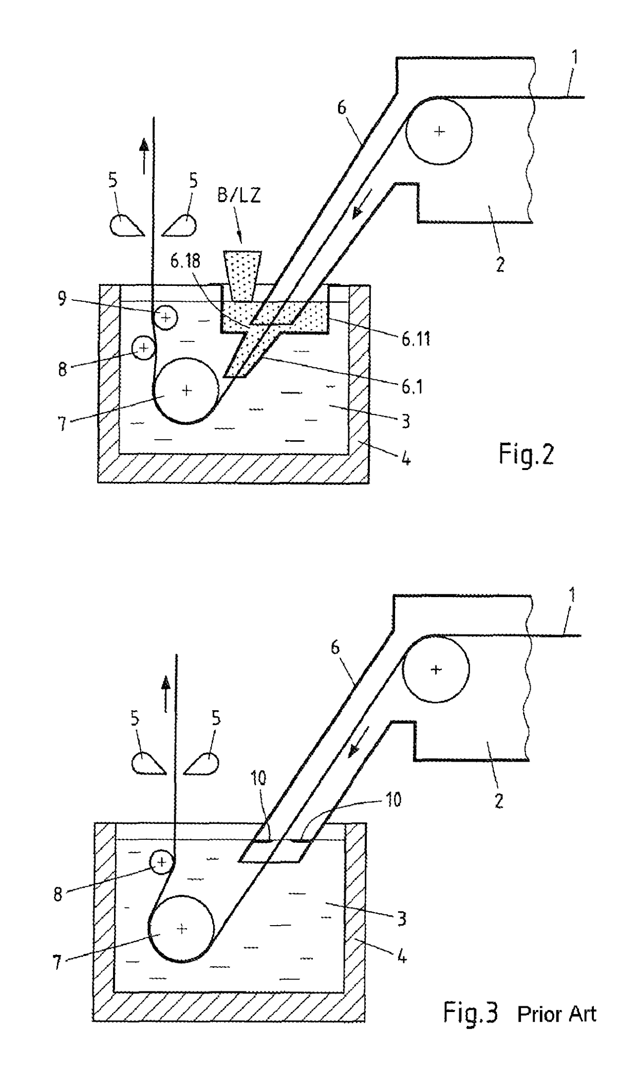
[0029]In the exemplary embodiments, illustrated in FIGS. 1, 2 and 5, of a device according to the invention for the hot-dip coating of metal strip, in particular steel strip, the snout 6 of a generic coating installation, which may correspond or corresponds substantially to the coating installation as per FIG. 3, is designed such that the immersed section of the snout 6 can have coating material B and / or at least one alloy additive LZ supplied to it separately. The device according to the invention is thus designed such that, in the region delimited by the snout 6, a melt can be implemented or used which is implemented differently, in terms of its chemical composition, than the chemical composition of the melt used in the melting bath 3.

[0030]For this purpose, the snout 6 is preferably equipped with a shaft-shaped snout elongation piece 6.1 for increasing the snout immersion depth. The snout elongation piece 6.1 has an attachment section 6.11 into which the lower end of the snout 6 ...


PUM

PropertyMeasurementUnit
thicknessaaaaaaaaaa
thicknessaaaaaaaaaa
thicknessaaaaaaaaaa

Abstract

A metallic flat product is disclosed which is subjected to surface finishing by hot-dip coating and which is preferably composed of steel. The metallic flat product includes a metallic alloy layer (11) and a metallic surface layer (12′), which metallic alloy layer and metallic surface layer differ from one another in terms of their chemical composition. The two layers (11, 12′) are produced in a one process step and define a continuous transition region (13) in which a mixture of the two different chemical compositions is present. The metallic alloy layer (11) has a thickness of less than 8 μm, preferably less than 6 μm, and the surface layer (12′) is formed from aluminum or zinc. The flat product has an improved coating, by means of which the flat product more effectively satisfies the requirements with regard to good deformability and has good anti-corrosion protection.

Description

CROSS-REFERENCE TO RELATED APPLICATIONS[0001]This application is the United States national phase of International Application No. PCT / EP2014 / 050091 filed Jan. 6, 2014, and claims priority to German Patent Application No. 10 2013 101 134.9 filed Feb. 5, 2013, the disclosures of which are hereby incorporated in their entirety by reference.BACKGROUND OF THE INVENTIONField of the Invention[0002]The invention relates to a metallic flat product which is subjected to surface finishing by hot-dip coating and which is preferably composed of steel, having a metallic alloy layer and having, on top of the latter, a metallic surface layer, which metallic alloy layer and metallic surface layer differ from one another in terms of their chemical composition, wherein the two layers are produced in one process step and define a continuous transition region in which a mixture of the two different chemical compositions is present, wherein the alloy layer has a thickness of less than 8 μm, preferably l...

Claims


Application Information

Patent Timeline
Patent Type & Authority Patents(United States)
IPC IPC(8): C23C2/06C23C2/40C23C2/12C23C28/02C23C30/00C23C2/04C23C2/02B32B15/01B32B15/04
CPCC23C2/06B32B15/012B32B15/013B32B15/016B32B15/017B32B15/04B32B15/043C23C2/02C23C2/04C23C2/12C23C2/40C23C2/405C23C28/02C23C28/021C23C28/023C23C28/025C23C28/028C23C30/00C23C30/005B32B15/01Y10T428/265Y10T428/1275Y10T428/12729Y10T428/12736Y10T428/12743Y10T428/12757Y10T428/12764Y10T428/12792Y10T428/12799Y10T428/12972Y10T428/12979Y10T428/2495Y10T428/24967Y10T428/24975Y10T428/26Y10T428/263Y10T428/264C23C2/00344C23C2/004
Inventor BERGEN, JEGORSPELLEKEN, FRANKPETERS, MICHAELRUTHENBERG, MANUELAMACHEREY, FRIEDHELMSPELZ, FLORIAN
Owner THYSSENKRUPP STEEL EURO AG
Learn More