

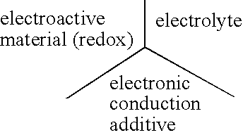
Electrode materials with high surface conductivity
a technology of surface conductivity and electrodes, applied in the direction of non-metal conductors, non-aqueous electrolyte cells, cell components, etc., can solve the problems of poor distribution of electrical potential within the electroactive material, excessive porosity and loss of operating efficiency of composite electrodes, and redox reactions resulting in the formation of several phases are usually not reversible, etc., to prevent potential reduction, improve the structure or crystallinity of carbonaceous deposits
- Summary
- Abstract
- Description
- Claims
- Application Information
AI Technical Summary
Benefits of technology
Problems solved by technology
Method used
Image

Examples
example 2
[0066] This example shows the formation of a conductive carbonaceous deposit from a hydrocarbon gas. The synthesis described in Example 1 for the preparation of lithium iron phosphate is repeated without adding polypropylene powder, and by replacing the thermal treatment inert atmosphere with a mixture of 1% propene in nitrogen. During the thermal treatment, propene decomposes to form a carbon deposit on the material being synthesized. The resulting sample obtained contains 2.5% of carbon, as determined by chemical analysis. Cyclic voltammetry is performed on this sample under the conditions described in Example 1 de carbon, and shows the important activation phenomenon during the first cycles (see FIG. 6). The improvement in redox kinetics is accompanied in this instance by an increase of the capacity reversibly exchanged. As measured during the discharge step, the initial capacity of the LiFePO, sample prepared represents 77% of the theoretical capacity, taking into account the 2....
example 3
[0068] The tryphilite sample LiFePO.sub.4 prepared above is analyzed. Its mass composition is: Fe: 34.6, Li: 4.2%, P: 19.2, which represents a 5% difference with respect to the stoichiometry.
[0069] The powder to be treated is impregnated with an aqueous solution of commercial sucrose, and dried. The amount of solution is selected to correspond to 10% of the weight of sucrose with respect to the weight of the material to be treated. Water is completely evaporated under agitation to obtain a homogeneous distribution. The use of sugar represents a preferred embodiment because it melts before being carbonized, thereby provided a good coating of the particles. Its relatively low carbon yield after pyrolysis is compensated by its low cost.
[0070] The thermal treatments are performed at 700.degree. C. under argon atmosphere. The temperature is maintained for 3 hours. Elemental analysis shows that this product contains 1.3% by weight of carbon Such thermal treatment leads to a black powder g...
example 4
[0071] Cellulose acetate is added to the phosphate LiFePO.sub.4 of Example 3 as a precursor of the carbon coating. This polymer is known to decompose with high carbonization yields, on the order of 24%. It decomposes between 200 and 400.degree. C. Above this temperature, the amorphous carbon rearranges to give a graphite-type structure that favors coherent and highly conductive carbon deposits.
[0072] Cellulose acetate is dissolved in acetone in a ratio corresponding to 5% by weight of the material to be treated, and dried before proceeding as above. The carbon concentration of the final product is 1.5%. The thermal treatment leads, in a similar manner, to a black powder having surface electronic conductivity, Its electroactivity, as measured on the 1.sup.rst (FIG. 8) and 5.sup.th (FIG. 9) charge-discharge cycles, is 152.6 mAhg.sup.-1 and 150.2 mAhg.sup.-1 respectively, which is 89.8% and 88.3% of the theoretical value. This value is to be compared with that of the product not coated...
PUM
| Property | Measurement | Unit |
|---|---|---|
| temperature | aaaaa | aaaaa |
| electronic conductivity | aaaaa | aaaaa |
| electronic conductivity | aaaaa | aaaaa |
Abstract
Description
Claims
Application Information