Back support for seat-backs, in particular for motor vehicle seats

a technology for seat backs and motor vehicles, which is applied in the direction of chairs, vehicle components, vehicle arrangements, etc., can solve problems such as being positioned outside of the suppor

Inactive Publication Date: 2001-05-08
MEGAPLAST SA
View PDF7 Cites 79 Cited by
  • Summary
  • Abstract
  • Description
  • Claims
  • Application Information

AI Technical Summary

Benefits of technology

is to design a backrest of the type specified as known in such a way that the drive is built small enough that it can be housed completely behind the arch of the support plate.

Problems solved by technology

Also known for this process is a motor drive, which however has the disadvantage that it must be housed outside of the support plate's area because of the size of the motor.

Method used


Image

  • Back support for seat-backs, in particular for motor vehicle seats
  • Back support for seat-backs, in particular for motor vehicle seats
  • Back support for seat-backs, in particular for motor vehicle seats

Examples


Embodiment Construction

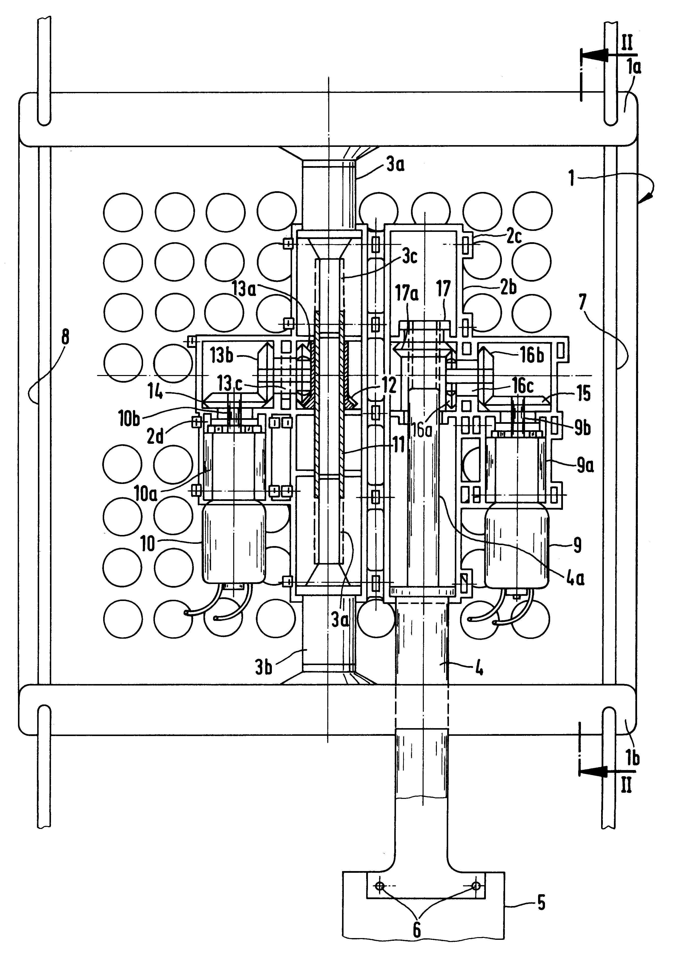
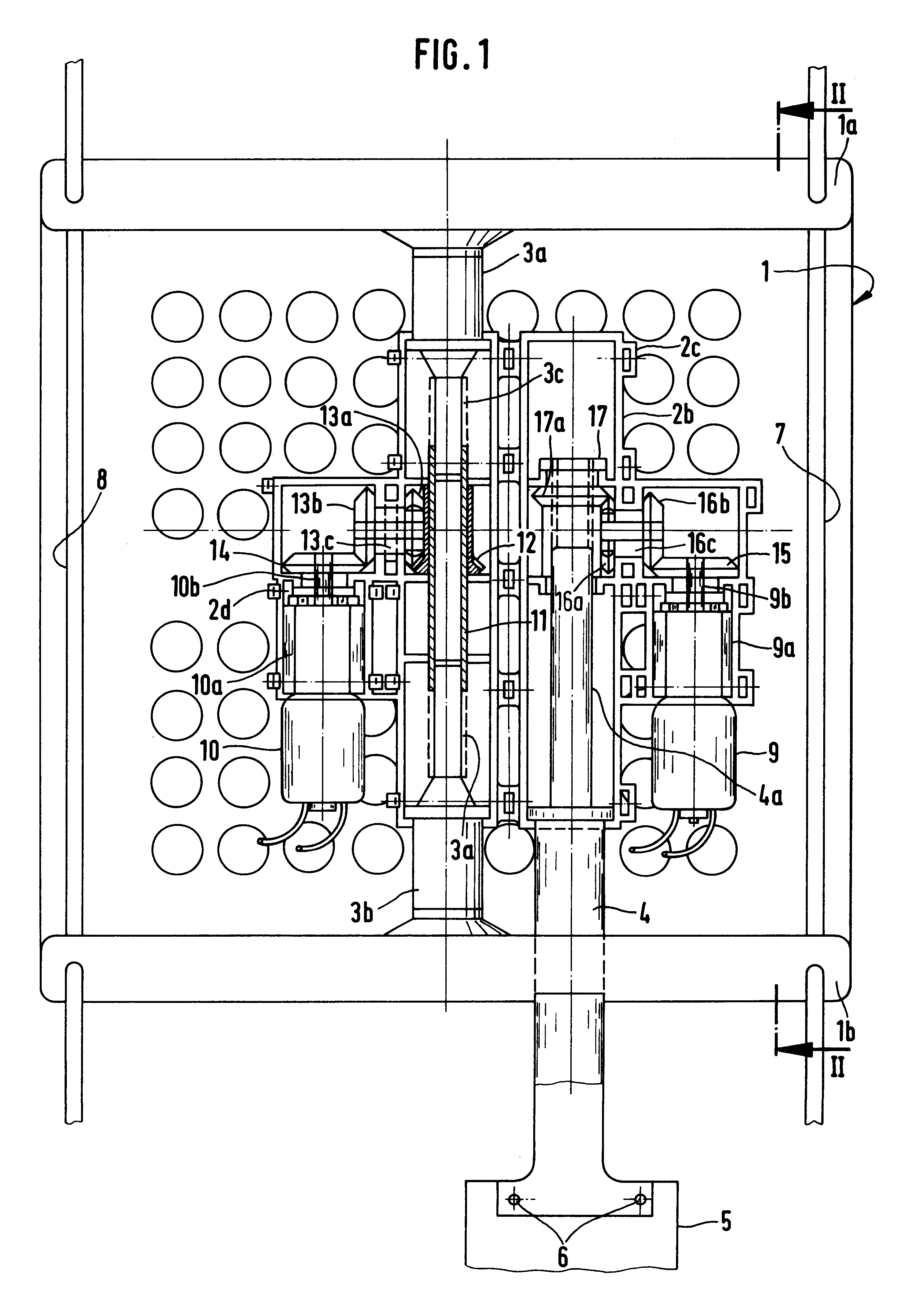
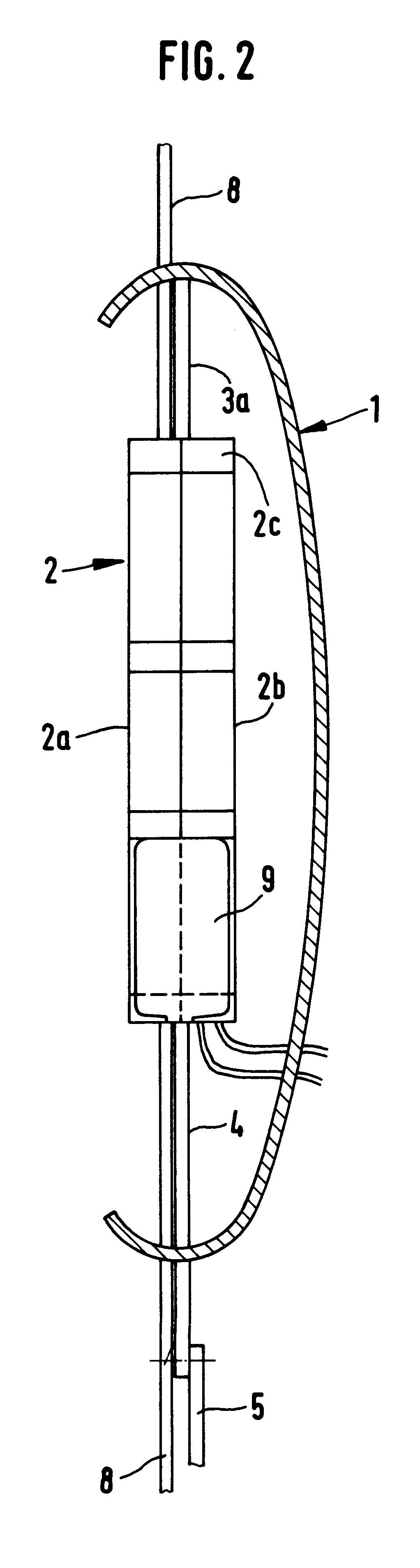
Designated as 1 is an arched support plate that arches forward in the direction of the user. The arch is adjustable in that the bracket areas 3a and 3b, which are attached to the upper and lower end regions of the support plate 1 that are bent toward the rear, are separated from one another by a shorter or longer distance.

The support plate 1 is carried in a height-adjustable manner on guide elements, which in the depicted example embodiment are guide wires 7 and 8, which pass through each of the upper and lower end regions 1a and 1b. The guide wires 7 and 8 are like-wise attached to the seat back, as is a bracket 4 that is connected by means of fastening elements (that are not shown) with a region 5 that is fixed with respect to the seat back. The bracket 4 serves for height adjustment of the support plate 1.

Adjustment of the arch is achieved through turning of a sleeve 11, which has inner thread regions of opposite handedness that engage around the appropriately designed outside th...


PUM


Abstract

A lumbar support for seat backs, in particular of motor vehicle seats, has a forward-bowed support plate (1). The support plate (1) is height-adjustable, moving upward and downward on guide organs that are fixed with respect to the seat back, and is also variable in its curvature through the use of a motor-driven tension bracket that can be lengthened or shortened. The tension bracket consists of bracket regions (3a and 3b) that act on upper end region (1a) and lower end region (1b) of the support plate (1). The bracket regions have thread regions of opposite handedness pointing toward one another which are externally engaged by a common rotatable sleeve (11) with appropriately designed meshing areas. The drive motor (10) is fixed to a gear case (2) arranged behind the support plate (1). The motor (10) drives gear wheels of a gearbox whose final gear wheel (13a) stands in engagement with the sleeve (11). The sleeve has inside thread regions of opposite handedness.

Description

The invention concerns a lumbar support for seat backs in accordance with the introductory clause of Claim 1.STATE OF THE ARTIn seat backs of this nature, it is known to adjust the arch of the support plate by means of a drive motor such that the crown of the support plate stands forward in the direction of the user's back to a greater or lesser extent. Also known for this process is a motor drive, which however has the disadvantage that it must be housed outside of the support plate's area because of the size of the motor.THE INVENTIONBased on this state of the art, the object of the invention is to design a backrest of the type specified as known in such a way that the drive is built small enough that it can be housed completely behind the arch of the support plate.This object is achieved with the features of the novelty portion of Claim 1.In addition to a motor drive solely for the arch of the support plate, it is also possible in the same manner to provide an additional motor dr...

Claims


Application Information

Patent Timeline
Patent Type & Authority Patents(United States)
IPC IPC(8): A47C7/46B60N2/64B60N2/66B60N2/90
CPCB60N2/66B60N2/666B60N2/6673
Inventor VON MOLLER, MORITZ
Owner MEGAPLAST SA
Why Eureka
Try Eureka