Method for management of cache page and medium having a cache page management program stored therein

Inactive Publication Date: 2001-05-15
NEC CORP
View PDF5 Cites 5 Cited by
  • Summary
  • Abstract
  • Description
  • Claims
  • Application Information

AI Technical Summary

Benefits of technology

With coming into widespread use of a non-stop continuous operation of the computer system, the operating configuration in which the online operation proceeds concurrently with the batch operation is increasing. In particular, in the batch operation, the disk space to which individual job's access is narrower and accessing occurs concentratedly in a shorter time. Therefore, the effect of the disk cache is felt to be promising.
That is, the accessed disk space cannot follow up with the rapidly changing environment such that entries with drastically lowered re-use probability are "seized" in the vicinity of the LRU position of the protection region, thus lowering the hit ratio of the cache.
It is an object of the present invention to overcome the aforementioned problem and to provide a method for supervising cache pages in which the conventional segment LRU method has the ability of activating the "seized" entries and a medium having a management program for cache pages stored therein.
Based on the aspects and features aforementioned of the present invention, the lowering in the probability of re-use of the entry / entries in the vicinity of the LRU position in the protection area is detected, and the entry / entries in that vicinity can be transferred to the examination area. Thus it provides an effect to recover the hit ratio of the cache.

Problems solved by technology

If the accessing pattern to the disk storage device is changed in this manner, a variety of problems are raised in the segment LRU method due to, for example, switching between batch jobs.
That is, the accessed disk space cannot follow up with the rapidly changing environment such that entries with drastically lowered re-use probability are "seized" in the vicinity of the LRU position of the protection region, thus lowering the hit ratio of the cache.

Method used


Image

  • Method for management of cache page and medium having a cache page management program stored therein
  • Method for management of cache page and medium having a cache page management program stored therein
  • Method for management of cache page and medium having a cache page management program stored therein

Examples


first embodiment

The information system embodying the present invention is similar in the hard or physical structure to that shown in FIG. 7.

That is, a disk control device 30 is interposed between a central processing unit 20 and disk storage devices 40 to 43 and is made up of a cache memory 33, an MPU 32, a ROM 31 etc.

The cache memory 33 includes a suitable number of cache pages of suitable sizes and an LRU table 33a for supervising the cache pages 33b. A program (control program 33a) for supervising the cache pages 33b is stored and saved in the ROM 31.

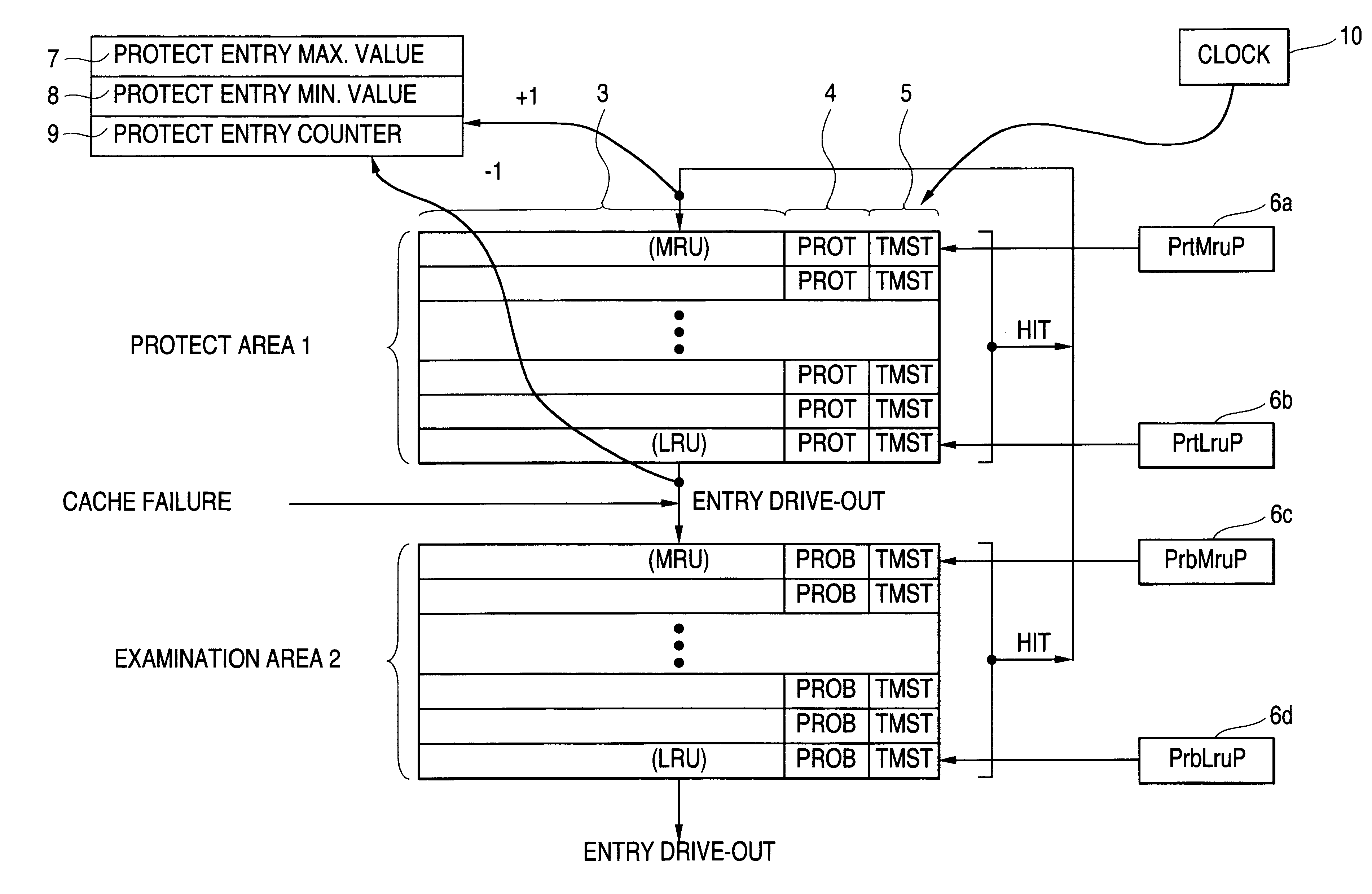
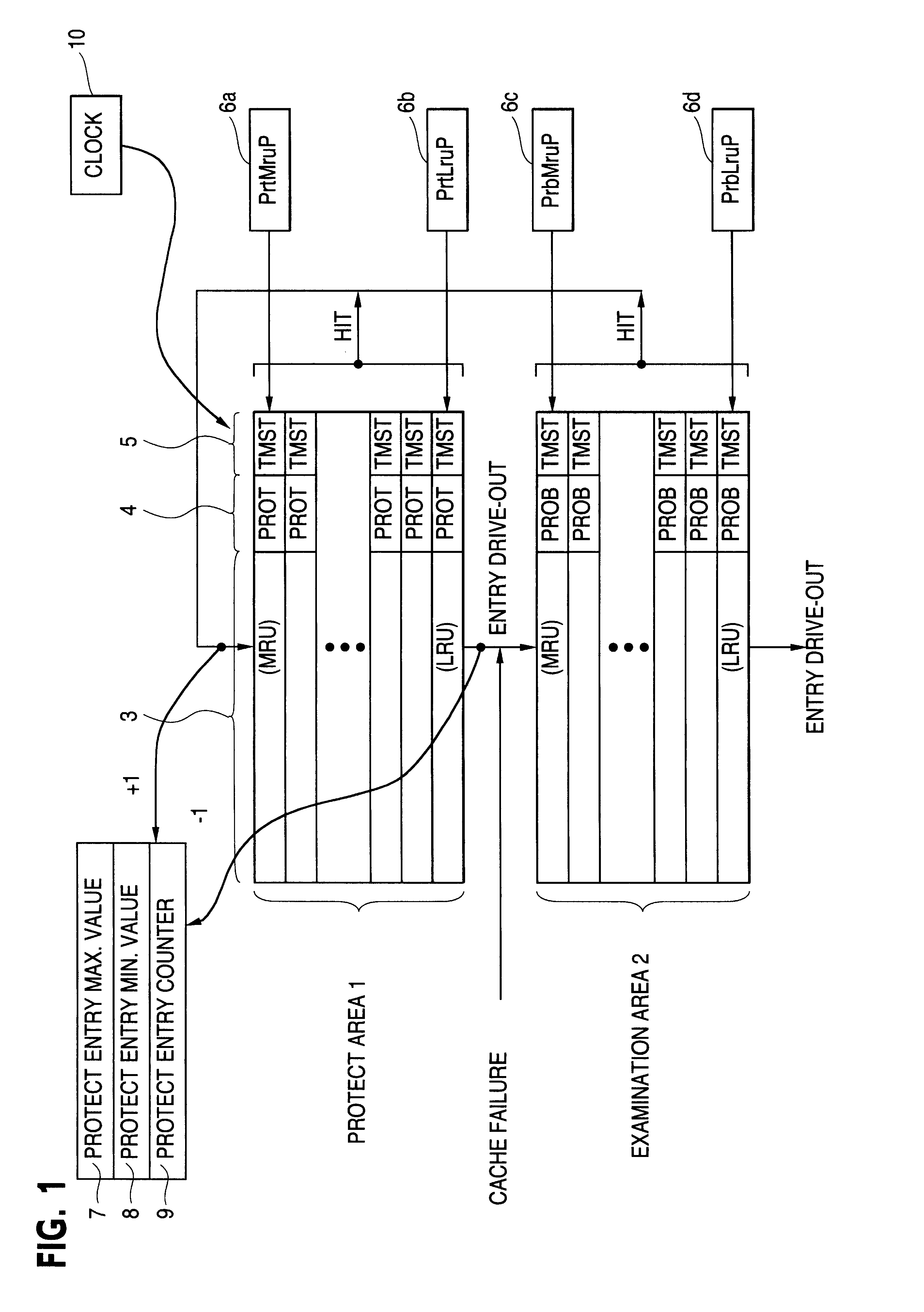
The schematics of the operation of the present embodiment are explained with reference to FIG. 1.

In the present embodiment, the structure of the conventional segment LRU method, shown in FIG. 8, has, in addition to the conventional segment LRU method, a protect entry maximum value register 7, for storing the maximum number of entries that can exist in the protection area 1 in the disk control device 30, a protect entry minimum value register 8, for ...

second embodiment

Referring to the drawings, a second embodiment of the present invention is explained. In the present embodiment, the hit ratio in the examination area 2 is used as a method for changing the size of the protection area 1 as the main point of the invention.

FIG. 4 illustrates the second embodiment of the present invention. As shown in FIG. 4, there are provided, in the second embodiment, in addition to the structure shown in FIG. 1, a newly added entry counter 11 for counting the number of times of addition of new entries 3 to the LRU table 33a on occurrence of cache failures, and an examination area hit counter 12 for counting the number of times of movement of the entries 3 to the protection area 1 by hits in the examination area 2.

As in the case of FIG. 1, constants are pre-set in the protect entry maximum value register 7 and in the protect entry minimum value register 8 upon initializing the cache.

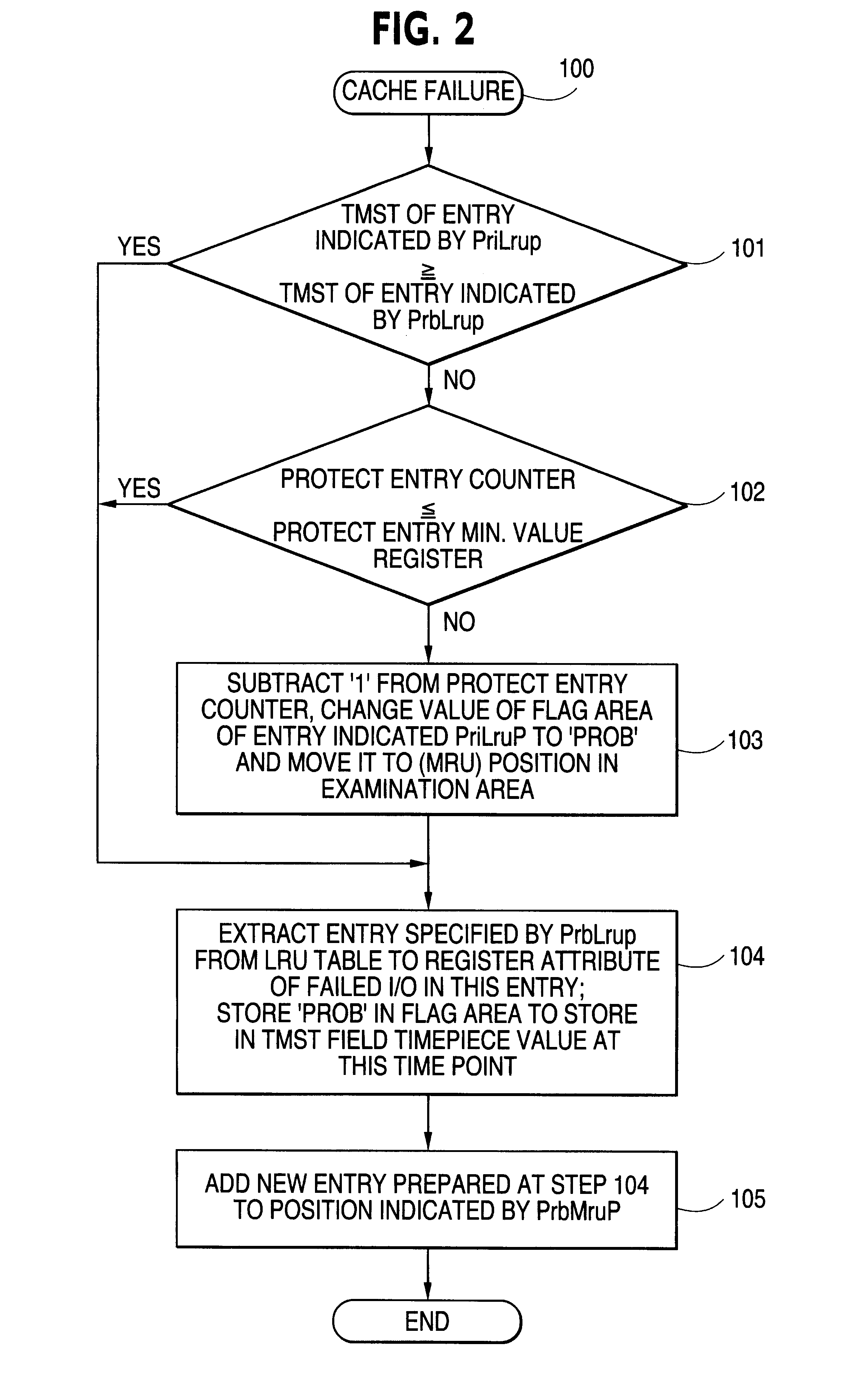
Referring to FIG. 5, the operation of the occasion of cache failures is explained.

Th...


PUM


Abstract

Conventional segment LRU are used to capture data entries. The time that each entry is most recently accessed is stored and held from one entry to another. If a central processing unit encounters a cache failure upon accessing the cache memory for writing or reading data to or from the storage device, the time point of storage of an entry at an LRU position in a protection area and that of an entry at an LRU position in an examination area are compared to each other. If the former is earlier, the entry at the LRU position in the protection area is moved to an MRU position in the examination area to reduce the size of protection area, while the cache failure entry is added to the MRU position in examination area and an entry at the LRU position in the examination area is driven out of the cache memory. If the latter is earlier, the entry at the LRU position in the examination area is extracted and driven out of the cache memory and the cache failure entry is added to the MRU position in the examination area.

Description

This invention relates to a method for management of cache ages and a medium having a cache page management program stored herein. More particularly, it relates to a method for management of cache pages used in a disk storage device and a medium having a cache page management program stored therein.DESCRIPTION OF THE RELATED ARTIn a cache page management method, used in a control device of the above type, it is one of crucial elements to raise the bit ratio of the cache while suppressing the cache memory capacity to a smaller value.For accomplishing this object, there is proposed a "Segment LRU method" such as is introduced in, for example, NIKKEI ELECTRONICS No. 617 (issued September 1994).Referring to FIG. 7, a general structure of a disk control device is explained.FIG. 7 is a block diagram showing a routine disk control device having a cache memory. As shown therein, a disk control device 30 is arranged between a central processing unit 20 and disk storage devices 40 to 43, andi...

Claims


Application Information

Patent Timeline
IPC IPC(8): G06F12/12G06F12/08G06F3/06
CPCG06F12/123G06F12/0866
Inventor UCHIDA, MITSUJIROU
Owner NEC CORP
Why Eureka
Try Eureka