
Front derailleur for a bicycle

a technology for derailleurs and bicycles, applied in mechanical devices, transportation and packaging, gearing, etc., can solve the problem that the above-noted position is not unnecessarily suited for an operation

Inactive Publication Date: 2001-05-22
SHIMANO SINGAPORE PRIVATE LTD
View PDF12 Cites 70 Cited by
  • Summary
  • Abstract
  • Description
  • Claims
  • Application Information

AI Technical Summary

Problems solved by technology

However, in a front derailleur having the fixed member disposed below the movable section, the above-noted position is not unnecessarily suited for an operation to attach the control cable to the pivotal link.

Method used


Image

  • Front derailleur for a bicycle
  • Front derailleur for a bicycle
  • Front derailleur for a bicycle

Examples


first embodiment

In view of the similarities between this embodiment and the prior embodiment, identical reference numerals will be utilized to refer to the parts of this embodiment that correspond to the Moreover, it will be apparent to those skilled in the art from this disclosure that the various parts and descriptions of the prior embodiments apply to the similar identical parts of this embodiment. Thus, the front derailleur 12 of this embodiment will not be discussed or illustrated in as much detail. Rather, it will be apparent to those skilled in the art from this disclosure that the various parts and descriptions of the prior embodiments apply to the similar or identical parts of this embodiment.

third embodiment

Referring now to FIG. 9, a third embodiment of the present invention is illustrated. This embodiment is similar to the prior embodiment, discussed above, except that the biasing member 35a of this embodiment has been modified to use a torsion spring instead of a coil spring.

In this embodiment, biasing member 35a is a torsion spring with its coiled portion wrapped around pivot pin 86. One end of the torsion spring 35a contacts first link 81, while the other end of torsion spring 35a contacts second link or vertical section 69 of chain guide 32. The torsion spring 35a is normally placed under tension to urge the cable guide 32 from its extended position to its retracted position. Of course, movement of chain guide 32 is controlled by shifting unit 16 moving cable 18 in a relatively conventional manner.

In view of the similarities between this embodiment and the prior embodiment, identical reference numerals will be utilized to refer to the parts of this embodiment that correspond to th...

fourth embodiment

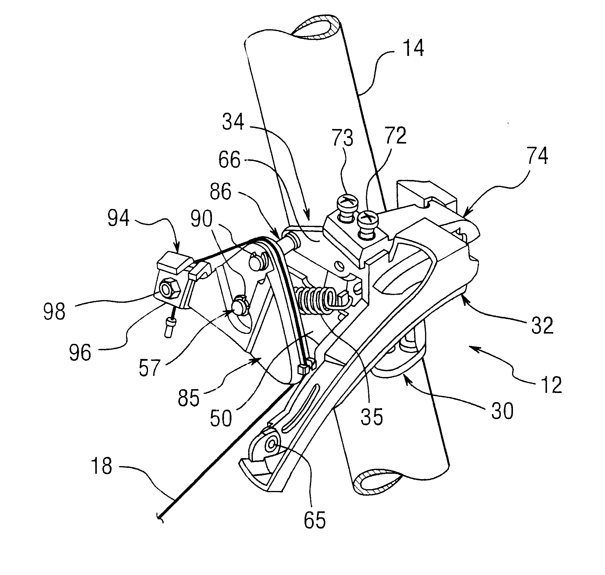
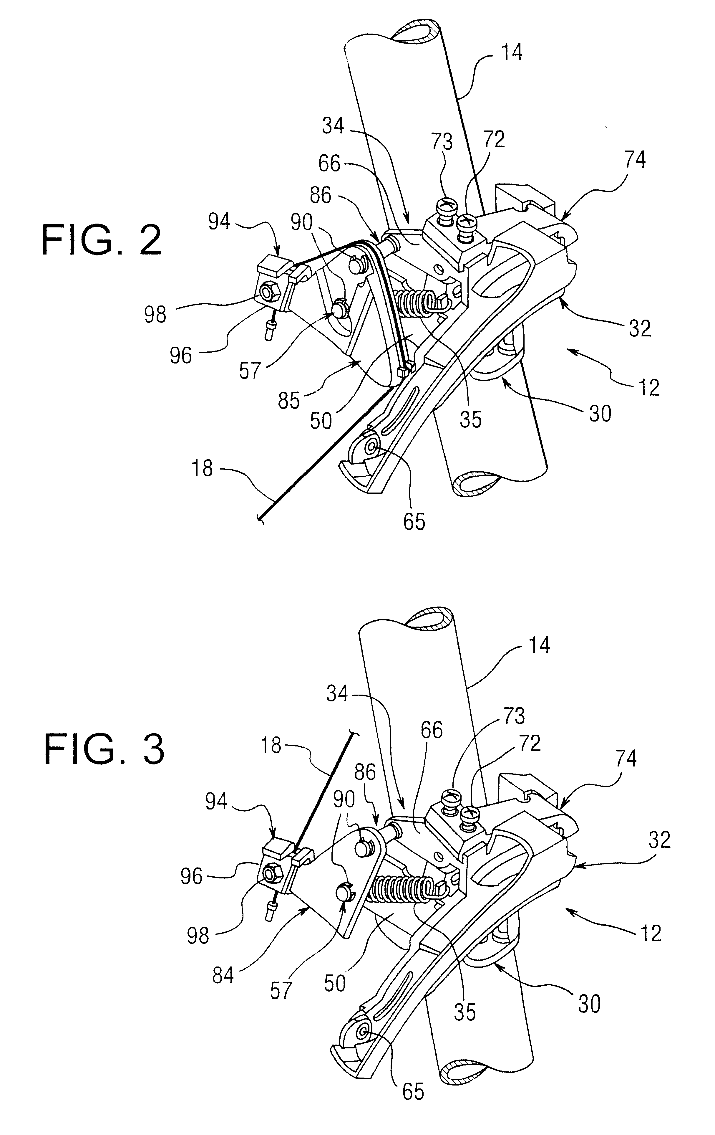
Referring now to FIG. 10, fourth embodiment of the present invention is illustrated. This embodiment is similar to prior embodiments, discussed above, except that the mounting arrangement for attaching the cable attachment member 84 and cable guide adapter 85 has been modified. Specifically, the pivot pins 86 and 57 of the first embodiment have been replaced with pivot pins 86a and 57a. Pivot pins 86a and 57a have external threads for receiving nuts 90a. Nuts 90a are preferably locking type nuts that engage the threads of pivot pins 86a and 57a such that they can be located at any point along the threads and they will not move due to vibrations or the like from bicycle 10. Pivot pins 86a and 57a are identical to pivot pins 86 and 57, discussed above, except that grooves 92 and 93 of pivot pins 86 and 57 have been replaced with external threads 92a in pivot pins 86a and 57a. Thus, pivot pins 86a and 57a will not be discussed or illustrated in further detail.

In view of the similaritie...


PUM


Abstract

A front derailleur for a bicycle is provided to move or shift a chain between two or more sprockets for changing gears. The front derailleur can be connected to the shift cable such that the shift cable is pulled upwardly or downwardly relative to the bicycle frame. The front derailleur has a fixed member adapted to be coupled to a portion of the bicycle, a chain guide for shiffing the chain of the bicycle and a linkage assembly coupled between the fixed member and the chain guide. The chain guide is located above the fixed member and a coil spring is used to bias the chain guide from an extended position to a retracted position. A detachable guide member is removably coupled to the linkage assembly for guiding the shift cable downwardly relative to the bicycle frame. If the detachable guide member is removed, then the shift cable is pulled upwardly relative to the bicycle frame.

Description

1. Field of the InventionThis invention generally relates to a front derailleur for a bicycle. More specifically, the present invention relates a front derailleur for a bicycle that can be used with many different shapes of bicycle frames.2. Background InformationGenerally, a front derailleur includes a fixed member nonmovably secured to a bicycle frame, and a movable section supported to be movable relative to the fixed member. The movable section supports a chain guide having a pair of vertical surfaces for contacting a chain.The movable section is movable relative to the fixed member by pulling a shift control cable. The movable section and fixed member usually are interconnected through pivotal links. The control cable is connected to one of the pivotal links to apply a torque thereto, thereby causing the links to move the movable section. The control cable is fixed to the link in such a position that an operating force applied to the control cable. This force on the cable is co...

Claims


Application Information

Patent Timeline
IPC IPC(8): B62M9/00B62M9/12B62M9/1342B62M9/137B62M9/1348
CPCB62M9/1342B62M9/1348B62M9/137
Inventor PENG, LEE CHER
Owner SHIMANO SINGAPORE PRIVATE LTD
Features
  • Generate Ideas
  • Intellectual Property
  • Life Sciences
  • Materials
  • Tech Scout
  • Unparalleled Data Quality
  • Higher Quality Content
  • 60% Fewer Hallucinations
Learn More