Torsional vibration damper

a technology of vibration damper and torsional force, which is applied in the direction of spring/damper, vibration suppression adjustment, rotary machine parts, etc., can solve the problems of limited rotational deflection of the two flywheel mass arrangements relative to one another, uncoupling or damping of torque fluctuations,

Inactive Publication Date: 2001-06-12
MANNESMANN SACHS AG
View PDF19 Cites 14 Cited by
  • Summary
  • Abstract
  • Description
  • Claims
  • Application Information

AI Technical Summary

Problems solved by technology

The relative rotation of the two flywheel mass arrangements is counteracted by a force determined essentially by the inert masses of the two flywheel mass arrangements and of the coupling mass arrangements and by the moments of inertia of the pendulum weights, thereby causing the uncoupling or damping of torque fluctuations.
However, the basic profile of the restoring force is not adaptable to any profile which may be desired, because the rest

Method used


Image

  • Torsional vibration damper
  • Torsional vibration damper
  • Torsional vibration damper

Examples


Embodiment Construction

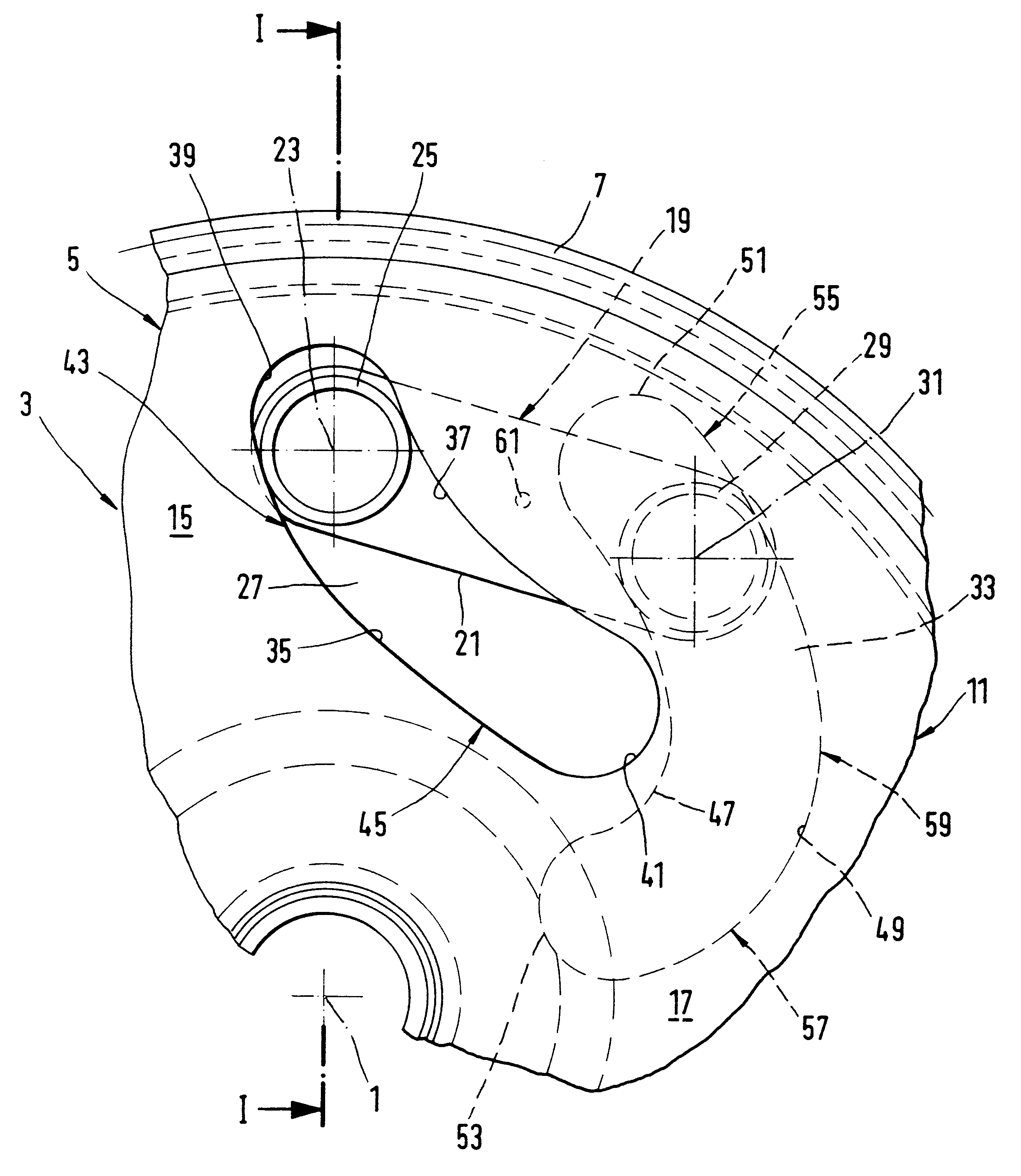
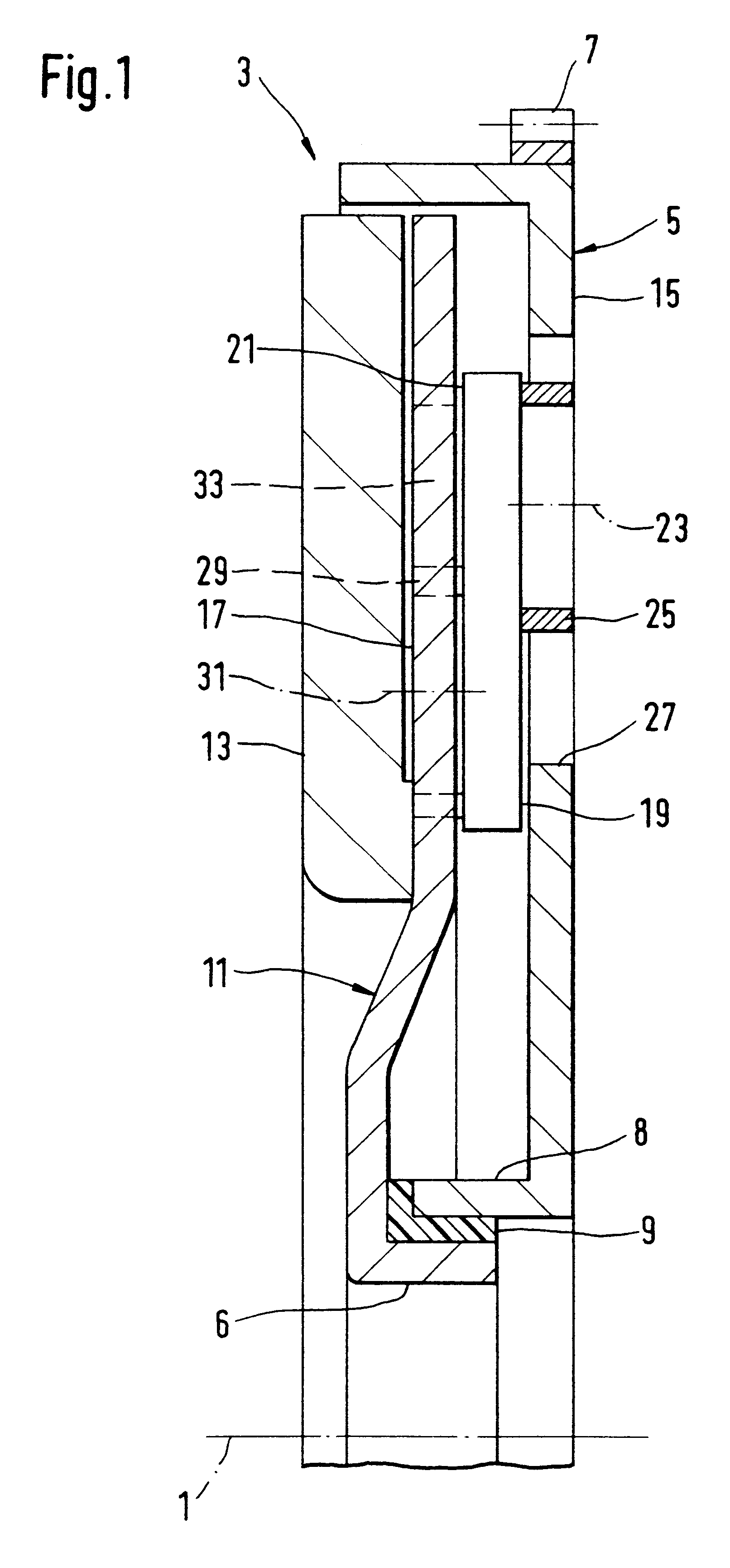
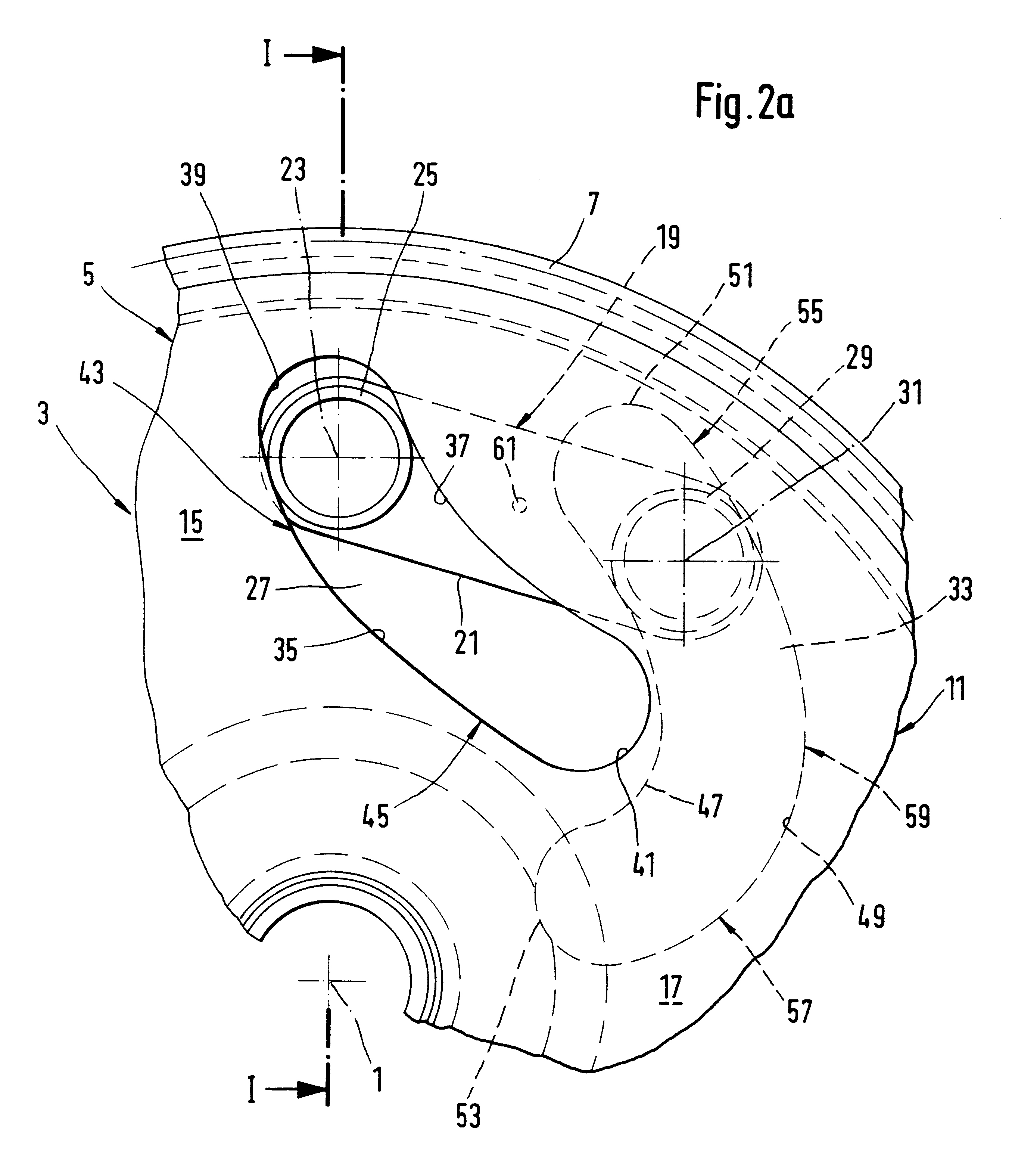
FIG. 1 shows a partial sectional view of a torsional vibration damper 3, rotatable about an axis of rotation 1. The torsional vibration damper 3 comprises a first flywheel mass arrangement 5 which is intended to be fastened to a crankshaft of an internal combustion engine of an automobile and which carries a starter gear ring 7 on its outer circumference, and a second flywheel mass arrangement 11, which has a clutch friction surface 13, rotatably mounted about the axis of rotation 1 on the first flywheel mass arrangement 5 by a rolling bearing 9. In this case, a hub part 6 of the second flywheel mass arrangement 11, the roller bearing 9 and a hub part 8 of the first flywheel mass arrangement 5 are arranged in radial outward succession.

The first flywheel mass arrangement 5 comprises a sheet metal part 15 radially extending between the starter gear ring 7 and the rolling bearing 9. The sheet metal part 15 is arranged an axial distance from a corresponding sheet metal part 17 of the se...


PUM


Abstract

A torsional vibration damper for a drive train of a motor vehicle comprises two flywheel mass arrangements which are rotatable both jointly and relative to one another about a common axis of rotation. The two flywheel mass arrangements are coupled by a coupling mass arrangement for transmitting torsional force. The coupling mass arrangement comprises a first bearing region movably mounted for translational motion along a first guide track on the first flywheel arrangement for transmitting torsional forces to the first flywheel mass. A second bearing region is arranged at a distance from the first bearing region on the coupling mass arrangement movable in translational motion along a second guide track on the second flywheel mass arrangement for transmitting torsional forces to the second flywheel mass.

Description

1. Field of the InventionThe invention relates to a torsional vibration damper for arrangement in a drive train of a motor vehicle.2. Description of the Related ArtFor the damping of torsional vibrations in the drive train of an automobile, prior art reference DE 42 00 174 A1 discloses a prior art torsional vibration damper comprising two flywheel mass arrangements which are rotatable both jointly and relative to one another about a common axis of rotation. Coupling mass arrangements that are uniformly distributed about the axis of rotation are used to couple the two flywheel mass arrangements for transmitting torsional forces therebetween. Each of the coupling mass arrangements includes a pendulum weight that is pivotally mounted on a first of the two flywheel mass arrangements about a pivot axis oriented parallel to the axis of rotation. In an operating state in which no torque is transmitted between the two flywheel mass arrangements, the pendulum weight is oriented essentially r...

Claims


Application Information

Patent Timeline
IPC IPC(8): F16F15/131
CPCF16F15/13157F16F15/13178Y10T74/2131Y10T74/2121
Inventor SUDAU, JORG
Owner MANNESMANN SACHS AG
Why Eureka
Try Eureka