Protection cap for fiber coupler

a protection cap and coupler technology, applied in the direction of optics, instruments, optical light guides, etc., can solve the problems of affecting the light transmission capability and accuracy affecting the appearance, and affecting the performance of the coupler 60

Inactive Publication Date: 2001-06-19
HON HAI PRECISION IND CO LTD
View PDF5 Cites 246 Cited by
  • Summary
  • Abstract
  • Description
  • Claims
  • Application Information

AI Technical Summary

Problems solved by technology

Once the housing 68 is soiled, the light transmission capability and accuracy of the coupler 60 may be adversely affected.
However, the plug 70 may be easily misplaced, and when the fiber plug is removed, the housing 68 is remains open to an exterior thereof and may become soiled.
Furthermore, since a laser beam continuously passes through the fiber, an operator's eyes may easily be injured after the plug 70 is removed.
Furthermore, the assembly of the coupler 80 is complicated because the metal plate 82 needs to be installed in the fastening recess 882 before the protecting lid 84 and the coil spring 86 are assembled which increases manufacturing costs.
This increases the manufacturing cost.
Furthermore, the mounting plate 82 is not securely attached to the housing 88 and may become lost after a period of usage.

Method used


Image

  • Protection cap for fiber coupler
  • Protection cap for fiber coupler
  • Protection cap for fiber coupler

Examples


Embodiment Construction

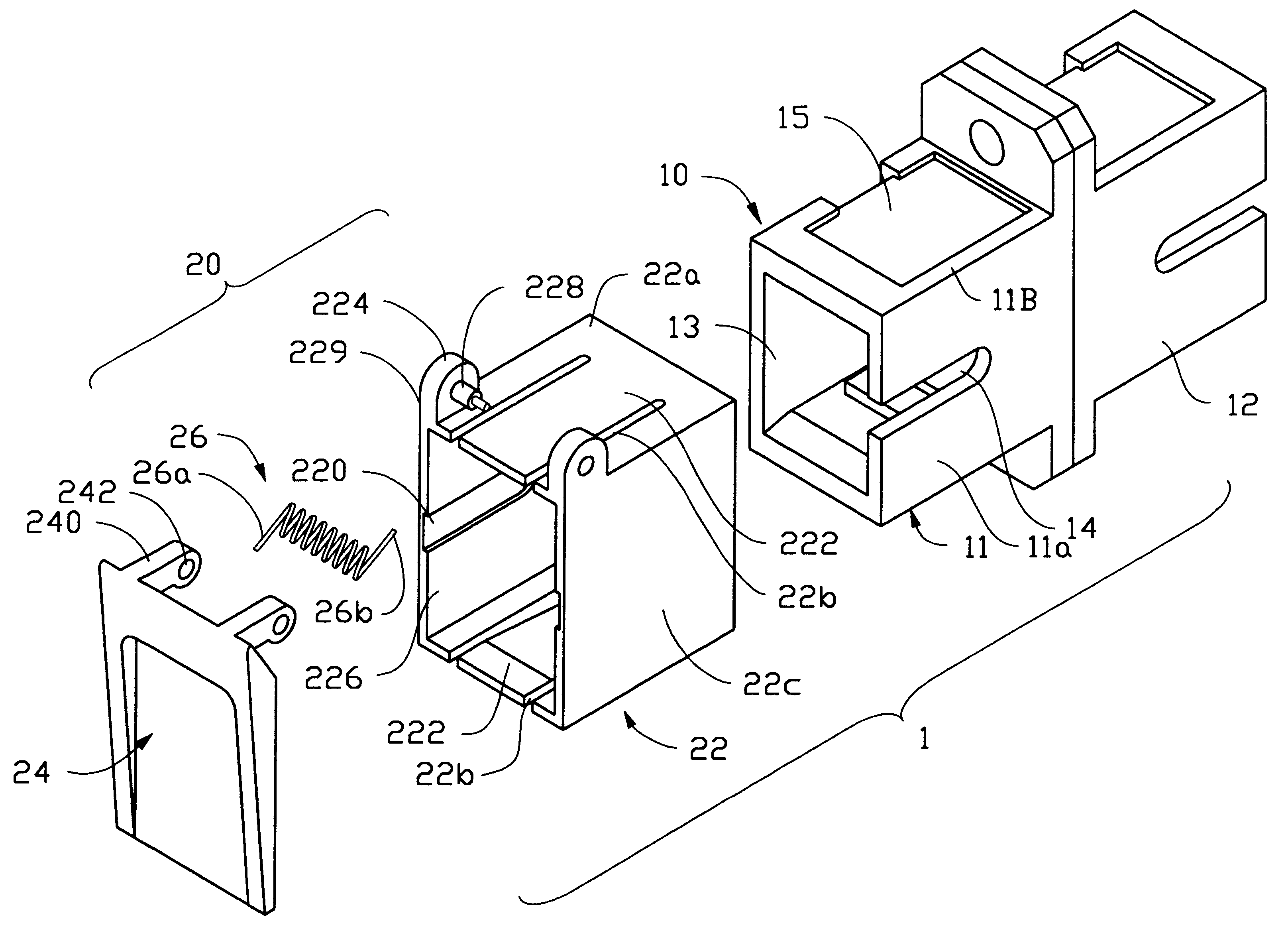
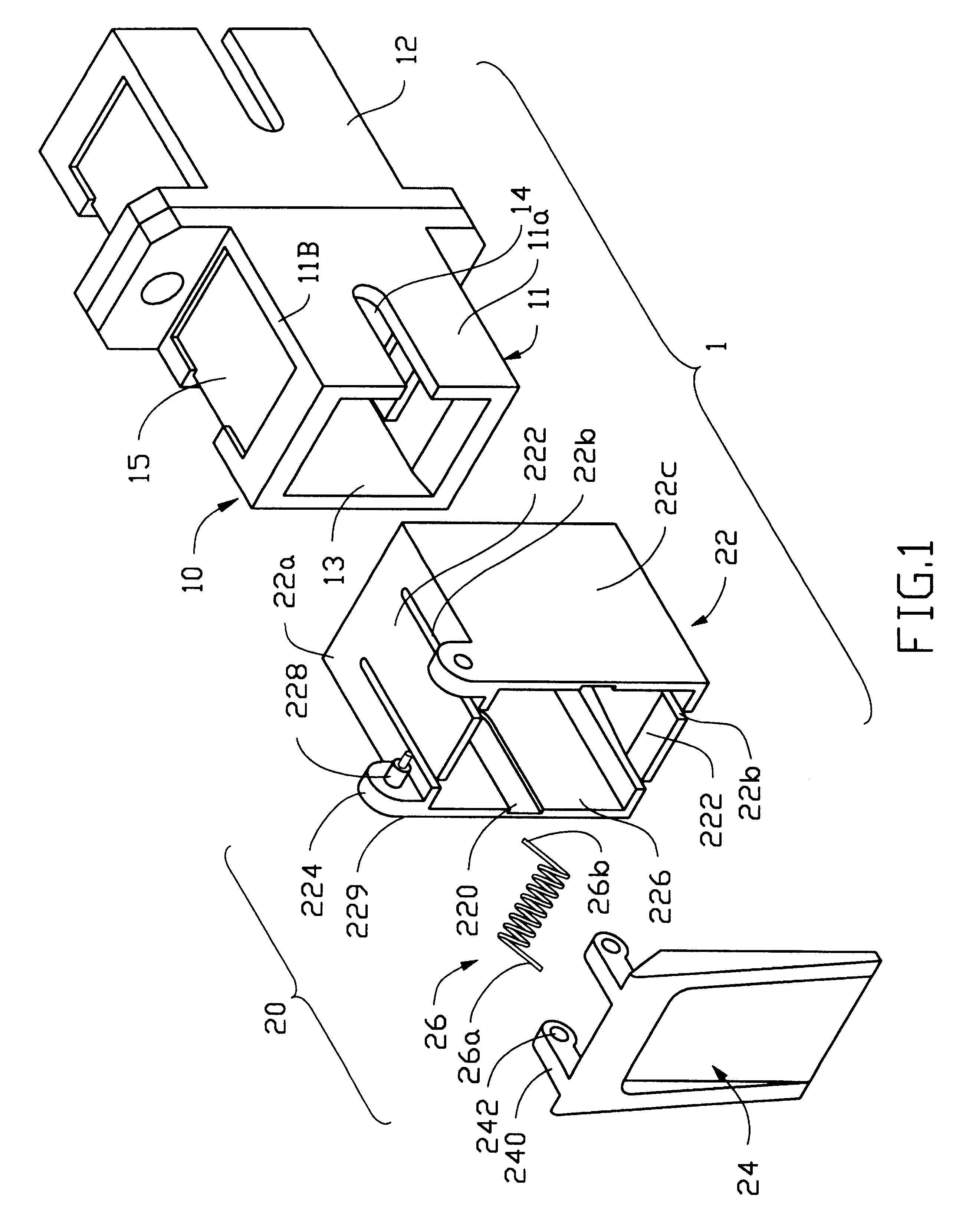
Referring to FIGS. 1 and 2, a fiber coupler 10 is assembled with a protection cap 20 to prevent the coupler 10 from being soiled.

The fiber coupler 10 includes a first housing 11 and a second housing 12 interconnected with each other. Since the first housing 11 and the second housing 12 have the same configuration, only the first housing 11 will be described.

The first housing 11 defines a receiving recess 13 for optically connecting a fiber plug therein. A guiding slot 14 is defined in a sidewall 11a of the housing 11. The housing 11 further defines a fastening recess 15 in a top face 11b thereof

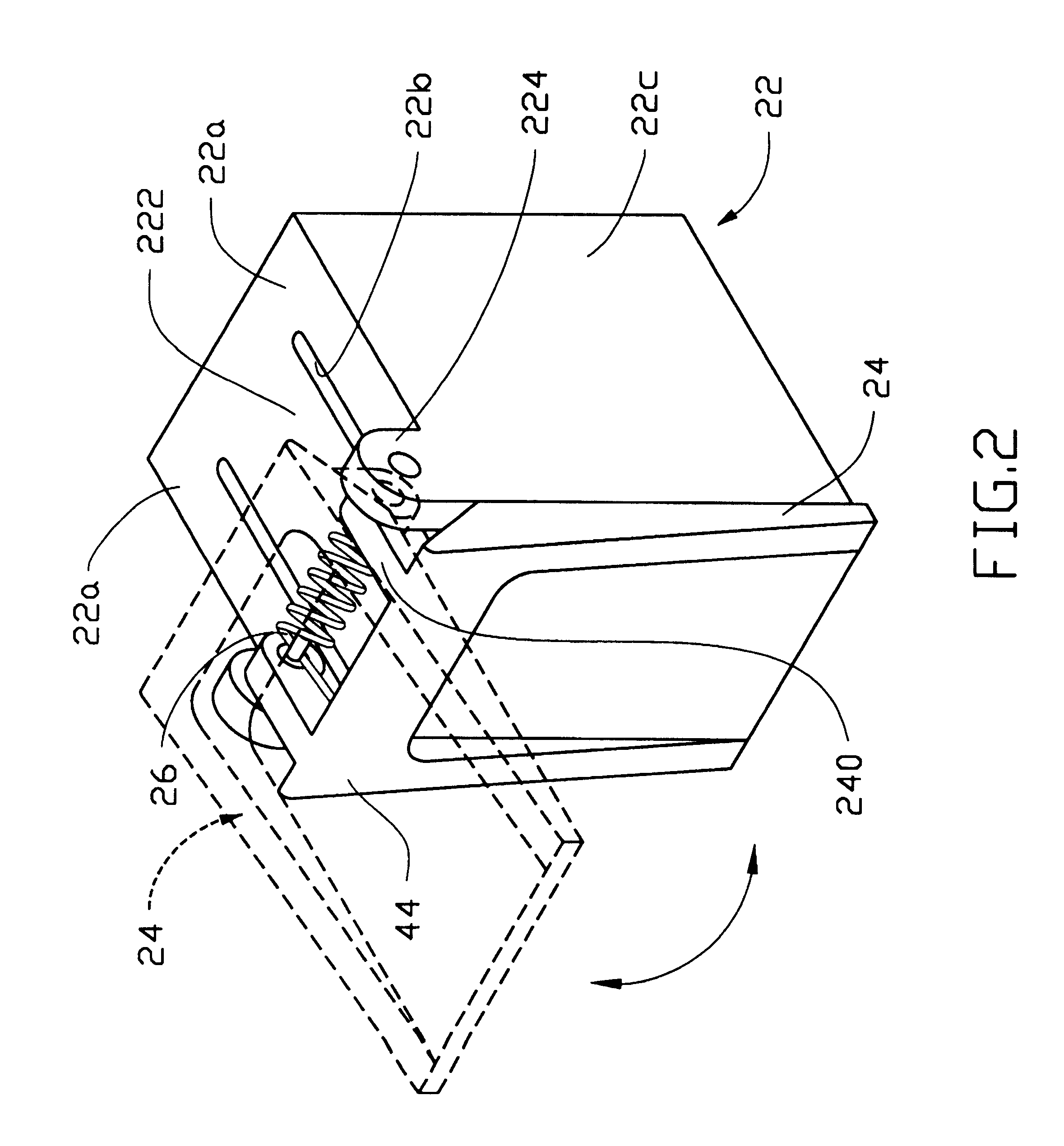
The protection cap 20 includes a casing 22, a covering lid 24 pivotally mounted to the casing 22, and a coil spring 26 providing a biasing force for the covering lid 24. The casing 22 defines a passage 226 for insertion of the housing 11 of the fiber coupler 10 may insert therein. A top face 22a of the casing 22 defines an opening 22b and an anchoring tab 222 is cantilevered from an edge ther...


PUM


Abstract

A protection cap for use with a fiber coupler having at least a first housing comprises a casing defining a passage therethrough for receiving at least a portion of the housing, and a covering lid pivotally assembled to the casing for enclosing an end of the passage.

Description

The present invention relates to a protection cap, and more particularly to a protection cap for a fiber coupler for preventing dust and foreign debris from soiling the fiber coupler.DESCRIPTION OF PRIOR ARTReferring to FIG. 3, a conventional fiber coupler 60 comprises a coupling housing 68. The coupling housing 68 defines a recess 66 for securely receiving a fiber plug (not shown) therein. A guiding slot 64 is defined on a sidewall 68a thereof for correctly receiving a guiding wedge (not shown) of the fiber plug. A top surface 68b of the housing 68 defines a retaining recess 62 for engaging with a fastening tab of the fiber plug. By this arrangement, the fiber plug can be fixedly attached to the housing 68 by the engagement between the fastening tab and the retaining recess 62.However, when the fiber plug is not inserted into the recess 66 of the housing 68, the recess 66 and the guiding slot 64 are exposed without any protection to an exterior thereof. Thus, dusts, debris and even...

Claims


Application Information

Patent Timeline
Patent Type & Authority Patents(United States)
IPC IPC(8): G02B6/38
CPCG02B6/3849G02B6/3825
Inventor LIU, CHING-YUAN
Owner HON HAI PRECISION IND CO LTD
Why Eureka
Try Eureka