Progressive lens

a technology of progressive lenses and lenses, applied in the field of progressive lenses, can solve the problem of not being able to vary with the specific optical requirements of the individual wearer, and achieve the effect of improving the optical performance of the lens element and low astigmatism

Inactive Publication Date: 2001-07-17
CARL ZEISS VISION AUSTRALIA HO
View PDF6 Cites 41 Cited by
  • Summary
  • Abstract
  • Description
  • Claims
  • Application Information

AI Technical Summary

Benefits of technology

The present invention provides a progressive ophthalmic lens element having a front surface that includes an upper viewing zone having a surface power suitable for distance vision, a lower viewing zone having a surface power suitable for near vision, and a corridor of relatively low astigmatism connecting the upper and lower viewing zones, the corridor being a part of an intermediate viewing zone having a surface power varying from that of the upper viewing zone to that of the lower viewing zone. The progressive ophthalmic lens element also has a back surface. The present invention is then characterised by the front surface including at least one correction to improve optical performance of the lens element by at least partially compensating for a cylinder correction applied to, or to be applied to, the back surface.

Problems solved by technology

Whilst these designs are a significant advance, they do not vary with the specific optical requirements of the individual wearer.

Method used


Image

  • Progressive lens
  • Progressive lens
  • Progressive lens

Examples


Embodiment Construction

The present invention will now be more fully described with reference to the accompanying examples. However, it should be understood that the following description is illustrative only and should not be taken in any way as a restriction on the generality of the invention described above.

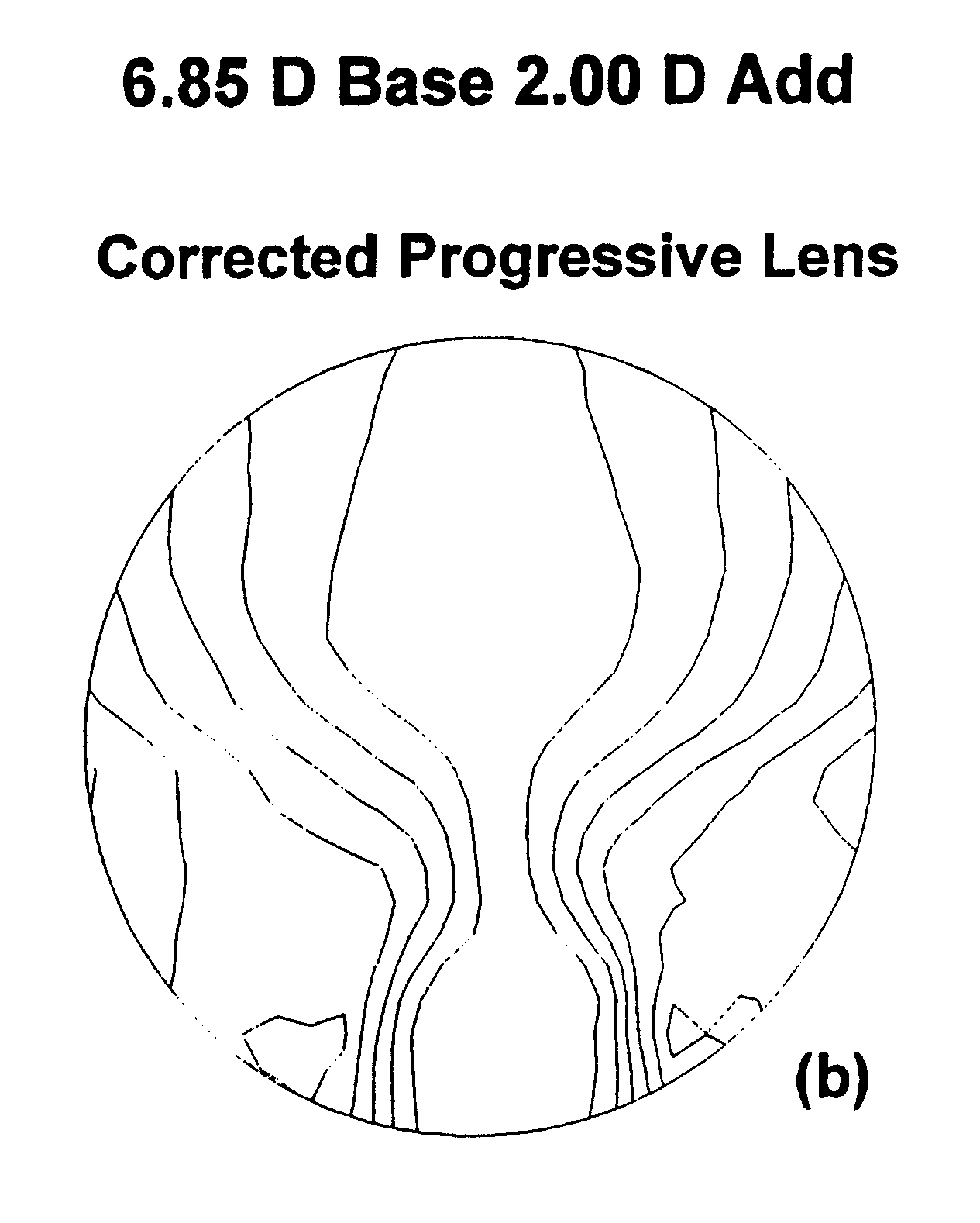
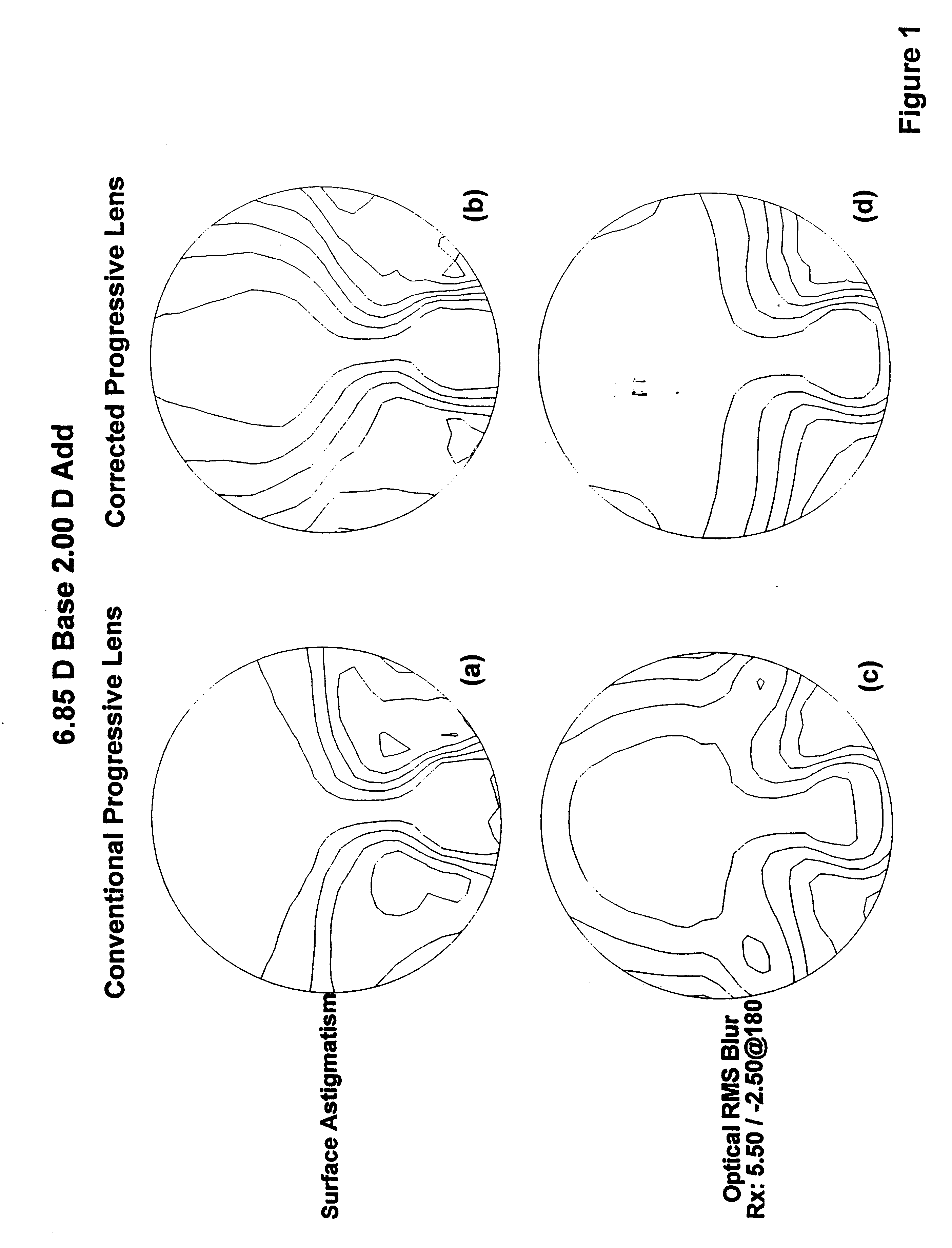
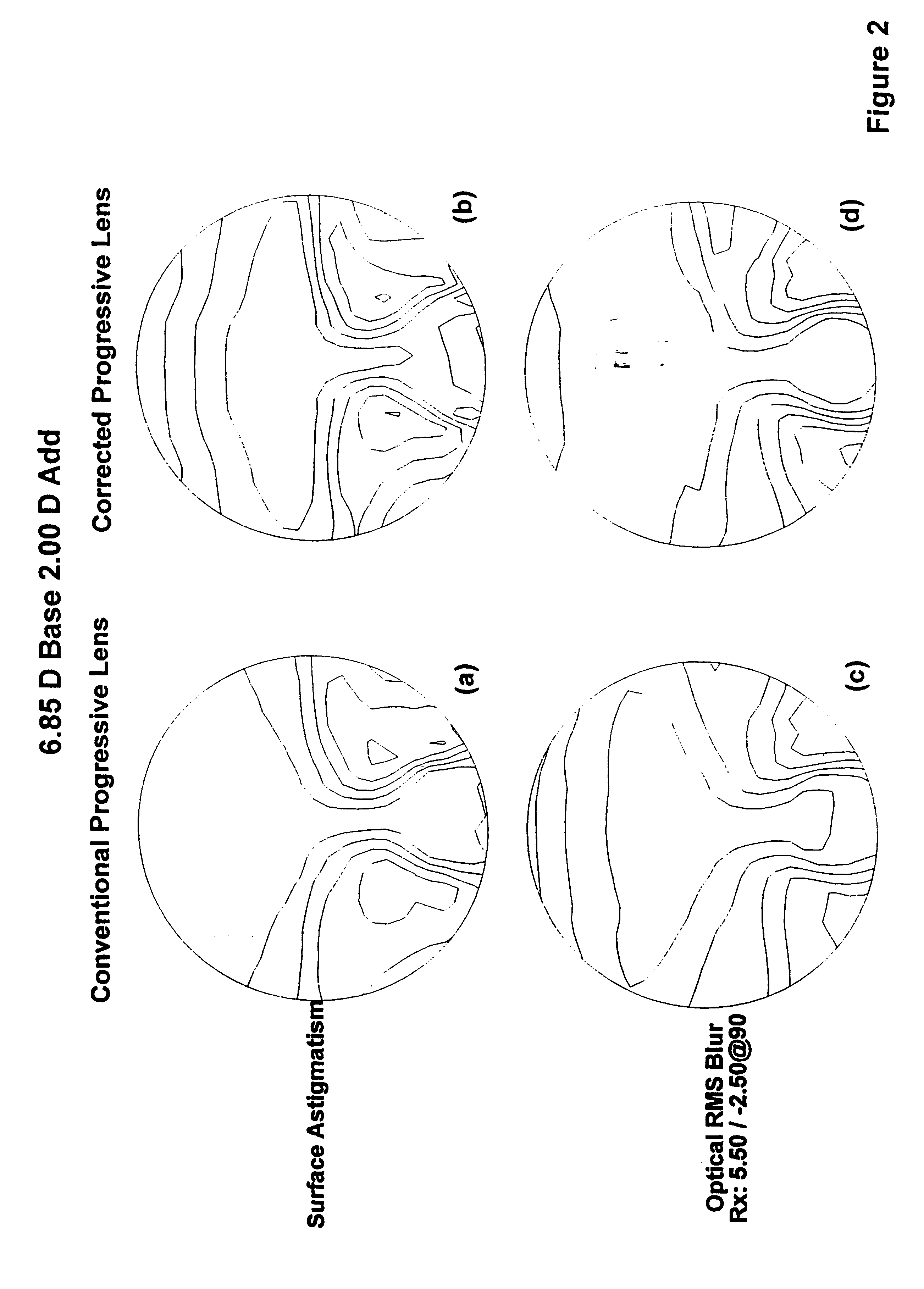
FIGS. 1 and 2 compare a conventional progressive lens and the progressive lens corrected according to the present invention for the -2.50 D cylinder prescription at two cylinder axis orientations, namely 180.degree. and 90.degree. respectively.

FIG. 3 shows a comparison of optical RMS blur contour plots of a conventional progressive lens and a progressive lens optimised for the -2.50 D at 180.degree. of cylinder. In particular, FIGS. 3(a) and 3(c) show the conventional progressive with values of prescription -2.00 D and -3.00 D of cylinder respectively. FIGS. 3(b) and 3(d) show the progressive lens in accordance with the present invention for the same prescription values where the front surface is the...


PUM


Abstract

A progressive ophthalmic lens element having a front surface that includes an upper viewing zone having a surface power suitable for distance vision, a lower viewing zone having a surface power suitable for near vision, and a corridor of relatively low astigmatism connecting the upper and lower viewing zones, the corridor being a part of an intermediate viewing zone having a surface power varying from that of the upper viewing zone to that of the lower viewing zone. The progressive ophthalmic lens element also has a back surface. The invention is then characterized by the front surface including at least one correction to improve optical performance of the lens element by at least partially compensating for a cylinder correction applied to, or to be applied to, the backsurface.

Description

The present invention relates to a progressive ophthalmic lens and in particular to the improvement of the progressive lens surface to compensate for cylinder correction applied to the non-progressive surface.BACKGROUND OF INVENTION AND OBJECTSNumerous progressive lenses are known in the prior art. Progressive lenses are typically designed to have distance, near and intermediate viewing zones where the intermediate zone joins the near and distance zones in a cosmetically acceptable way, such that no discontinuities in the lens are visible to people observing the wearer.Significant advances in customising progressive lens design have been disclosed in international patent application PCT / EP97 / 00105. This application describes a series of lens elements where the progressive designs vary depending on whether the wearer is a myope (short-sighted), emmetrope (normal vision) or hyperope (long sighted), whilst maintaining substantially constant the optical field of vision in the near and / o...

Claims


Application Information

Patent Timeline
Patent Type & Authority Patents(United States)
IPC IPC(8): G02C7/02
CPCG02C7/061G02C7/068G02C2202/08
Inventor EDWARDS, SIMON JOHNVARNAS, SAULIUS RAYMONDSKLAR, DAVID H.
Owner CARL ZEISS VISION AUSTRALIA HO
Why Eureka
Try Eureka