Device for filling receptacles and fitted with an integrated cleaning device

a technology for cleaning devices and receptacles, which is applied in the direction of liquid bottling, liquid dispensing, packaging goods, etc., can solve the problems of gaskets not being compressed sufficiently, cleaning substances to leak, and material components of sealing gaskets suitable for withstanding cleaning substances are generally relatively hard, so as to improve the effectiveness of sealing and improve the effect of sealing

Inactive Publication Date: 2001-07-31
SERAC GROUP
View PDF11 Cites 39 Cited by
  • Summary
  • Abstract
  • Description
  • Claims
  • Application Information

AI Technical Summary

Benefits of technology

This provides a structure which is compact and the helical motion of the rigid assembly makes it possible to bring the shutter member progressively up to the through orifice of the collector pan and to apply the shutter member firmly against the collector pan, thereby ensuring good sealing when shut. In addition, the axial component of the helical motion coincides with the direction in which force needs to be pressed against the shutter member, thereby reinforcing the effectiveness with which it shuts.
Advantageously, the shutter member is disposed inside the collector pan. The pressure of the cleaning substance flowing via the delivery duct thus contributes to pressing the shutter member against the collector pan, thereby reinforcing the effectiveness with which the through orifice is shut in leakproof manner.

Problems solved by technology

Unfortunately, the materials constituting the sealing gasket and which are suitable for withstanding cleaning substances are generally relatively hard.
There is therefore a risk that after passing through the hard point the sealing gasket will no longer be compressed sufficiently, thereby allowing the cleaning substance to leak.
Furthermore, the assembly constituted by the shutter member and the toggle mechanism is complex and bulky.
When the device is to perform sterile filling, the assembly runs the risk, because of its bulk, of disturbing the flow of sterile gas that flows around the filling device.

Method used


Image

  • Device for filling receptacles and fitted with an integrated cleaning device
  • Device for filling receptacles and fitted with an integrated cleaning device
  • Device for filling receptacles and fitted with an integrated cleaning device

Examples


Embodiment Construction

With reference to the figures, the filling device of the invention comprises a series of filling heads, and only the inside portion of one of them is shown in the figures.

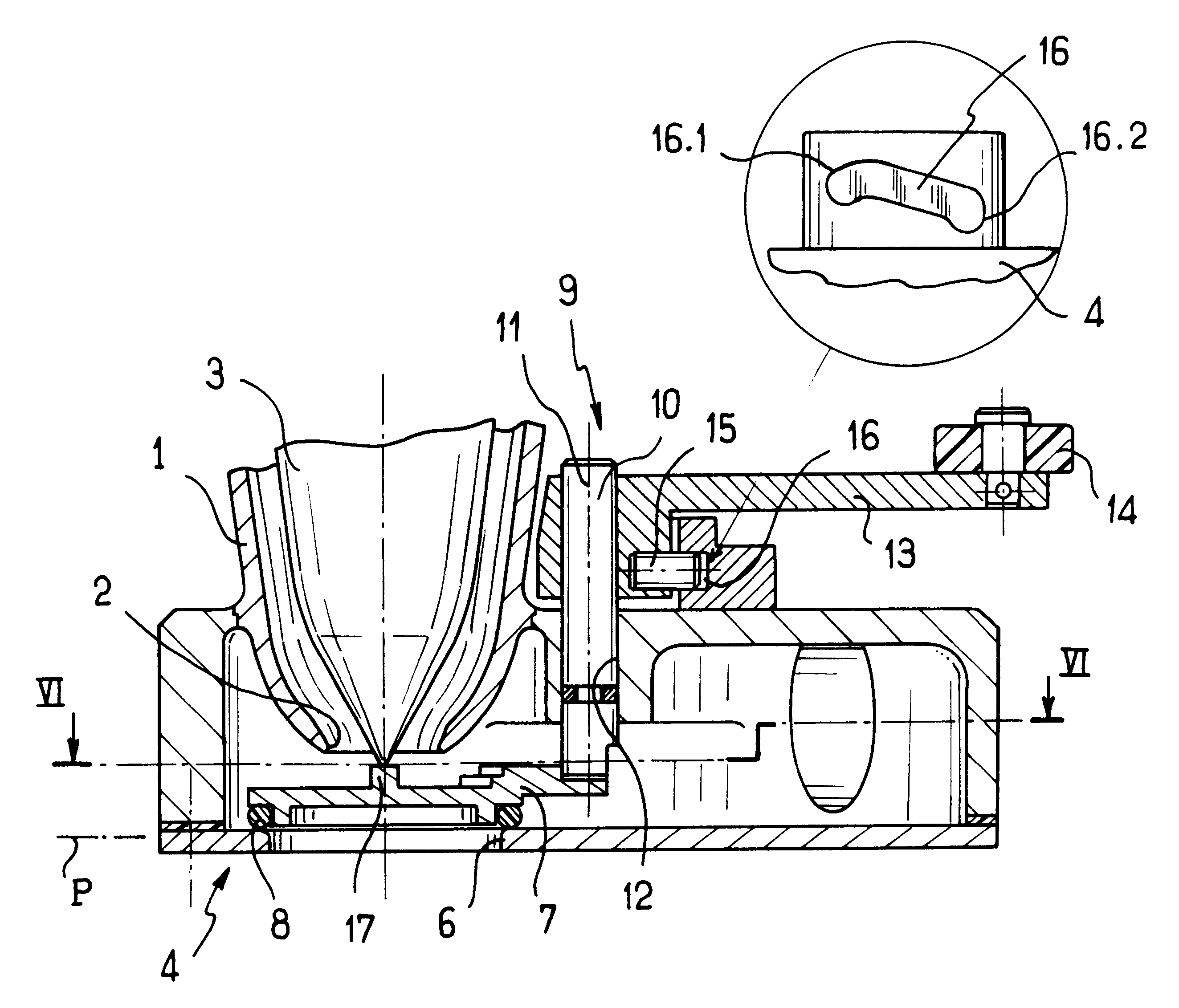
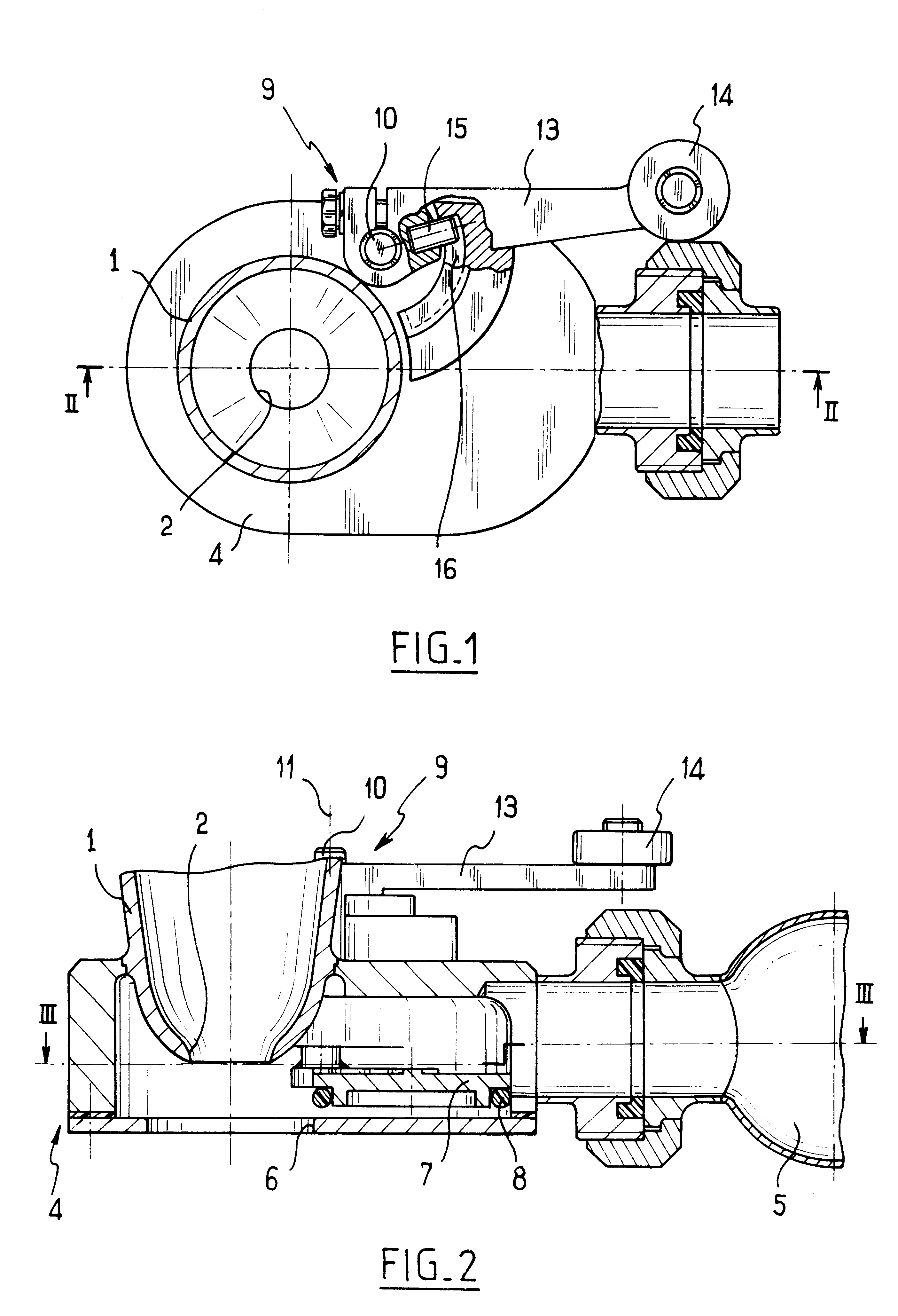
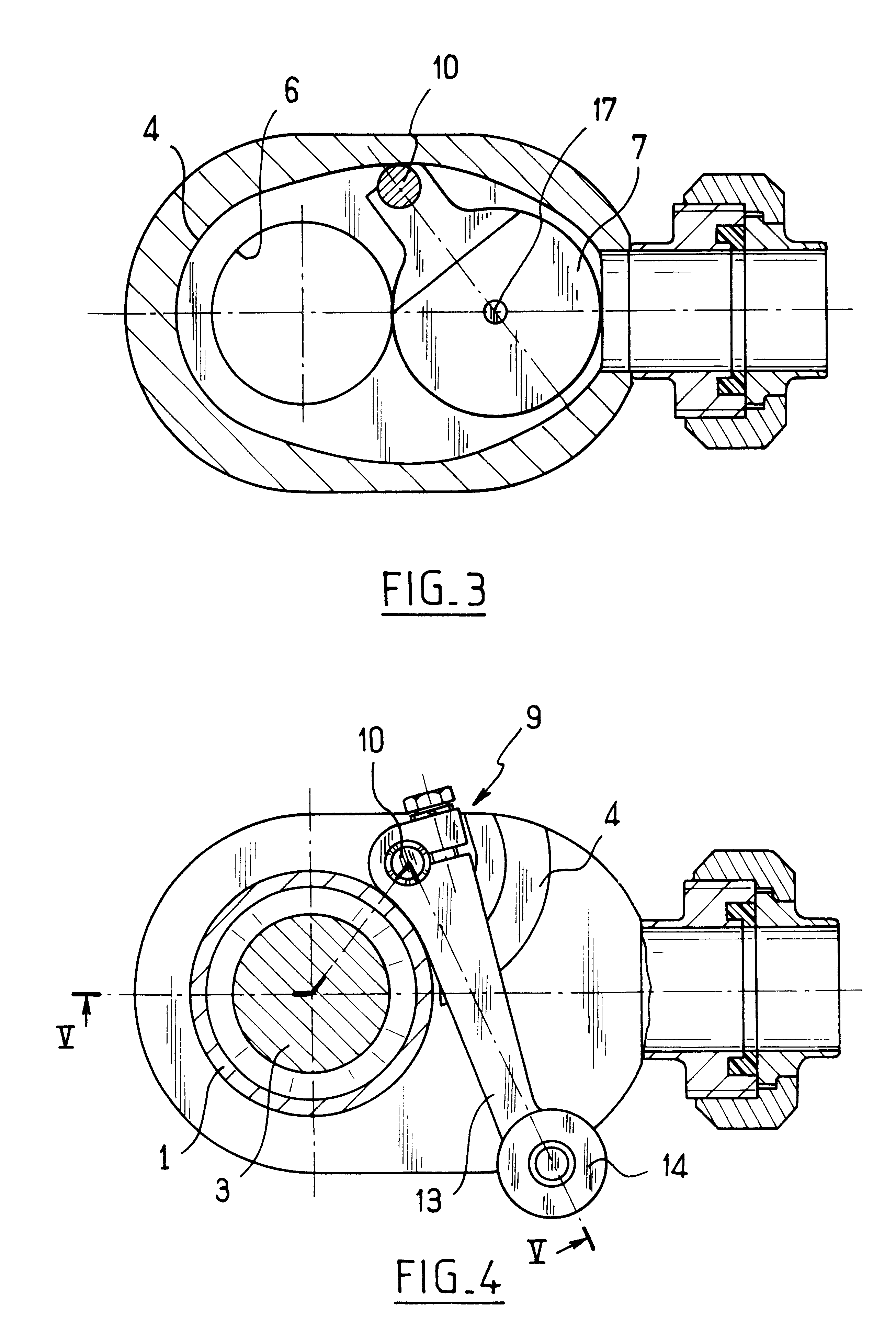
In conventional manner, the bottom portion of each filling head comprises a delivery duct 1 whose bottom end includes a flow orifice 2 associated with a plug 3.

Each filling head is associated with an integrated cleaning device comprising a collector pan 4 fixed in sealed manner to the delivery duct 1 in the vicinity of the flow orifice, e.g. by welding. The collector pan 4 is connected to a general collector manifold 5 common to all of the filling heads. The bottom portion of the delivery duct 1 is engaged inside the collector pan 4 which has a through orifice 6 disposed vertically in register with the flow orifice 2. A shutter member 7 provided with a sealing O-ring 8 is associated with the through orifice 6 and is movable between a position in which it shuts the through orifice 6, with the sealing O-ring being pr...


PUM

PropertyMeasurementUnit
hard pointaaaaaaaaaa
hardaaaaaaaaaa
flattening forceaaaaaaaaaa

Abstract

The filling device comprises a delivery duct having a flow orifice associated with a plug, and a cleaning device comprising a collector pan fixed in leakproof manner to the delivery duct in the vicinity of the flow orifice and having a through orifice vertically in register with the flow orifice and a shutter member fixed to an actuator member so that together they form a rigid assembly which is mounted to move with helical motion about an axis normal to a plane containing the through orifice, the shutter member being off said axis.

Description

The present invention relates to a deice for filling receptacles, which device includes an integrated cleaning device.BACKGROUND OF THE INVENTIONA filling device, e.g. a carousel, is known, in particular from document FR-A-2 720 733, which device comprises a series of filling heads each fitted with an integrated cleaning device. The cleaning device has a collector pan fixed in leakproof manner to the delivery duct of each filling head in the vicinity of a flow orifice therefrom, the collector pan having a through orifice disposed vertically in register with the flow orifice. The cleaning device has a shutter member carrying a sealing gasket and connected to a member for actuation via a resilient toggle so as to be movable between a disengaged position allowing the filling device to operate normally, and a position in which the through orifice is shut so as to allow the delivery duct to be cleaned by a substance flowing from the delivery duct into the collector pan, and filling it. S...

Claims


Application Information

Patent Timeline
Patent Type & Authority Patents(United States)
IPC IPC(8): B67C3/00
CPCB67C3/001B05B15/50
Inventor GRUSON, BERTRANDBIGO, SAMUEL
Owner SERAC GROUP
Why Eureka
Try Eureka