

Motor drive circuit
a technology of motor drive and circuit, applied in the direction of motor/generator/converter stopper, dynamo-electric converter control, polyphase induction motor starter, etc., can solve the problems of less reliable, expensive and complicated controllers using microprocessors and associated electronics, and conventional techniques for generating 120-degree phase differen
- Summary
- Abstract
- Description
- Claims
- Application Information
AI Technical Summary
Problems solved by technology
Method used
Image

Examples
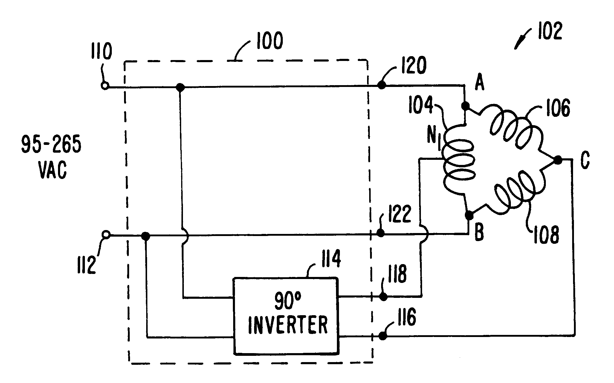
embodiment 100
The embodiment 100 has two input power terminals 110, 112 that are coupled to the single phase input supply from the utility company (typically 120 VAC). The input terminals 110, 112 are coupled to output terminals 120 and 122. A 90 degree inverter 114 is coupled between the input terminals 110, 112 and produces an output at output terminals 116 and 118. The output terminal 118 is coupled to motor terminal N, where N is the center point (center tap) of the winding 104. The output terminal 116 is coupled to the motor terminal C, the output terminal 122 is coupled to the motor terminal B and the output terminal 120 is coupled to the motor terminal A.
The inverter 114 produces an output voltage with a 90-degree phase difference with respect to the incoming phase. Thus, three phase power is provided and applied to the motor appropriately to result in three-phase balanced voltages applied on the three-phase windings of the motor.
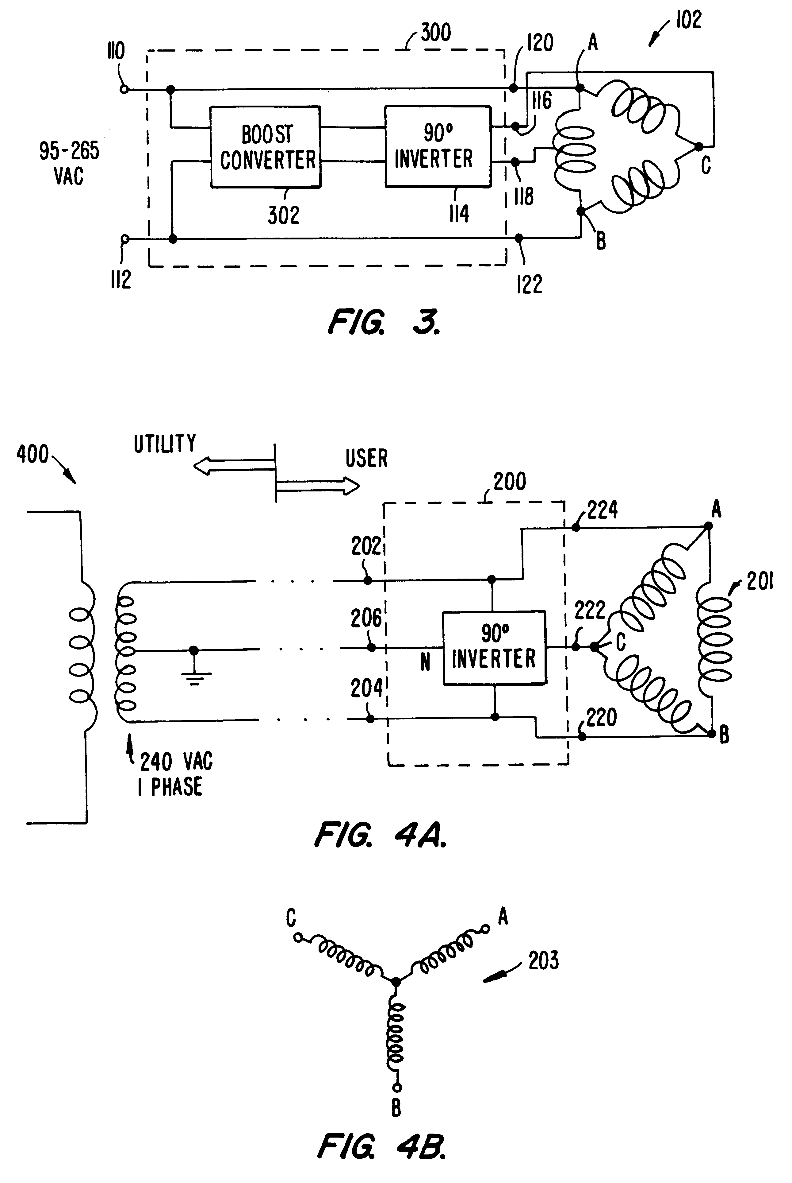
In another embodiment of the invention, an inverter is used ...
embodiment 200
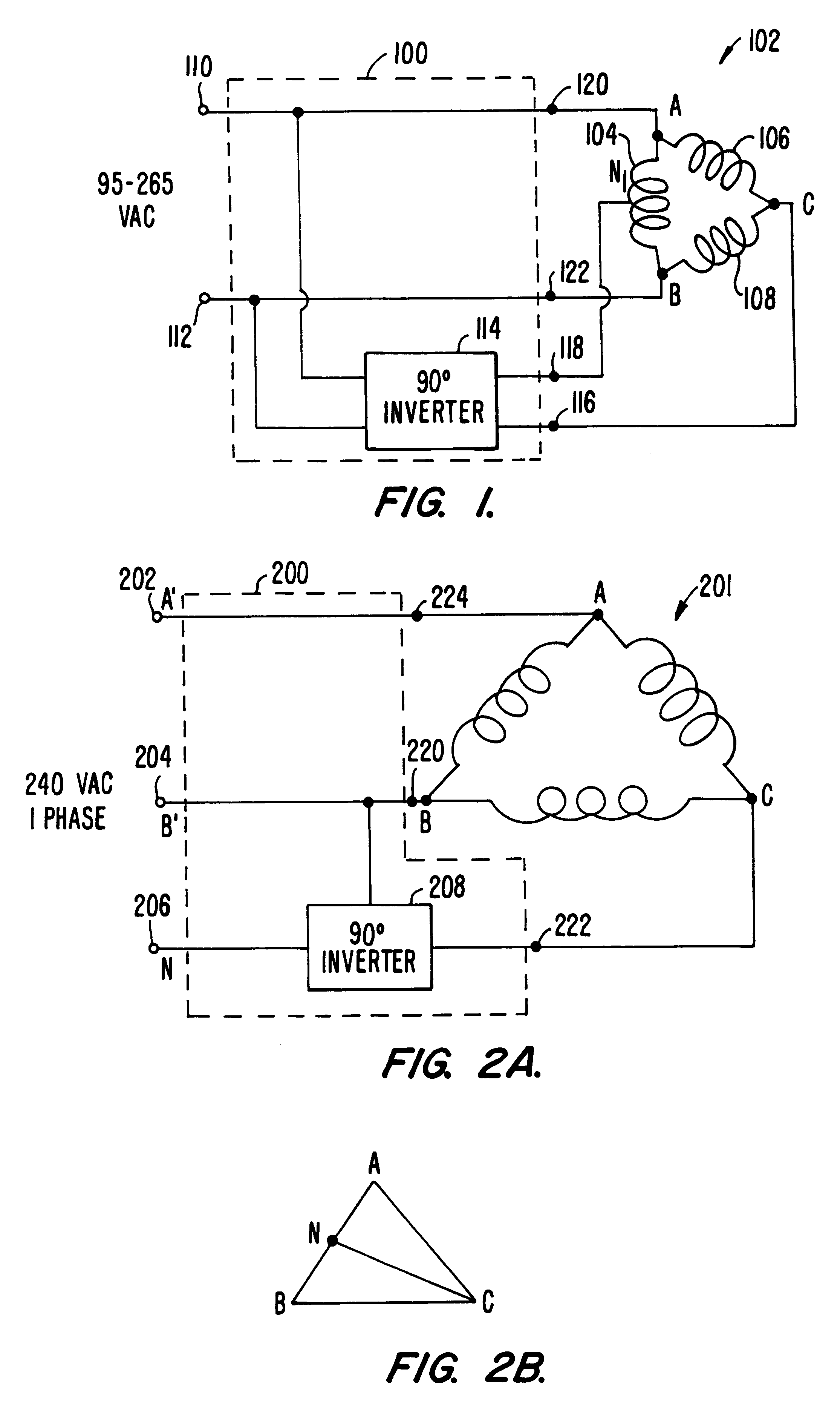
FIG. 2A shows a diagram of embodiment 200 of the present invention for use with 240 VAC single phase power. The 240 VAC single phase input power is converted to three phase power for input to a motor 201, having a delta configuration. The input power is received at terminals 202, 204 and 206. The terminals 202 and 204 are coupled to the 240 VAC single phase AC supply (A', B') and the terminal 206 is coupled to the neutral (N).
A 90 degree phase inverter 208 is coupled to the input power and supplies current to one phase connection of the motor at coupled at output terminals 220, 222. Output terminal 224 is also coupled to the motor. A 90-degree voltage is generated by the inverter, which makes the control circuitry simple and inexpensive. Note that only about one half of the motor's power flows through the inverter, which allows the inverter to be one half the size required than if all the power flowed through the inverter. Conventional single- to three-phase converters typically car...
PUM
 Abstract
Description
Claims
Application Information