Timepiece

a technology of timepieces and fitting pins, applied in the field of timepieces, can solve the problems of inability to make major changes in design, complicated overall impression of display parts, etc., and achieve the effects of reducing the length of fitting pins, and sufficient attachment strength

Inactive Publication Date: 2001-08-14
SEIKO EPSON CORP
View PDF15 Cites 51 Cited by
  • Summary
  • Abstract
  • Description
  • Claims
  • Application Information

AI Technical Summary

Benefits of technology

In this case, it is preferable that the aforementioned fitting pin comprises: a base portion having a bottom plane form which approximately matches the bottom portion of the aforementioned receiving recession; a tip portion which protrudes from the aforementioned receiving recession and which is configured so as to fit with the aforementioned dial; and an intermediate portion which has a tapered form so as to secure space for an adhesive to pool. Inserting the base of the fitting pin into the receiving recession and injecting an adhesive agent or the like into the receiving recession allows the precision of attachment of the fitting pin to the covering to be improved and sufficient attachment stren

Problems solved by technology

However, with such multi-functional wristwatches, the indicating area of the time-of-day display system which encompasses almost the entirety of the display portion, and the sub-display system are positioned so as to overlap in a plane, meaning that the needles of the time display system and the sub-indicating area of th

Method used


Image

  • Timepiece
  • Timepiece
  • Timepiece

Examples


first embodiment

[First Embodiment]

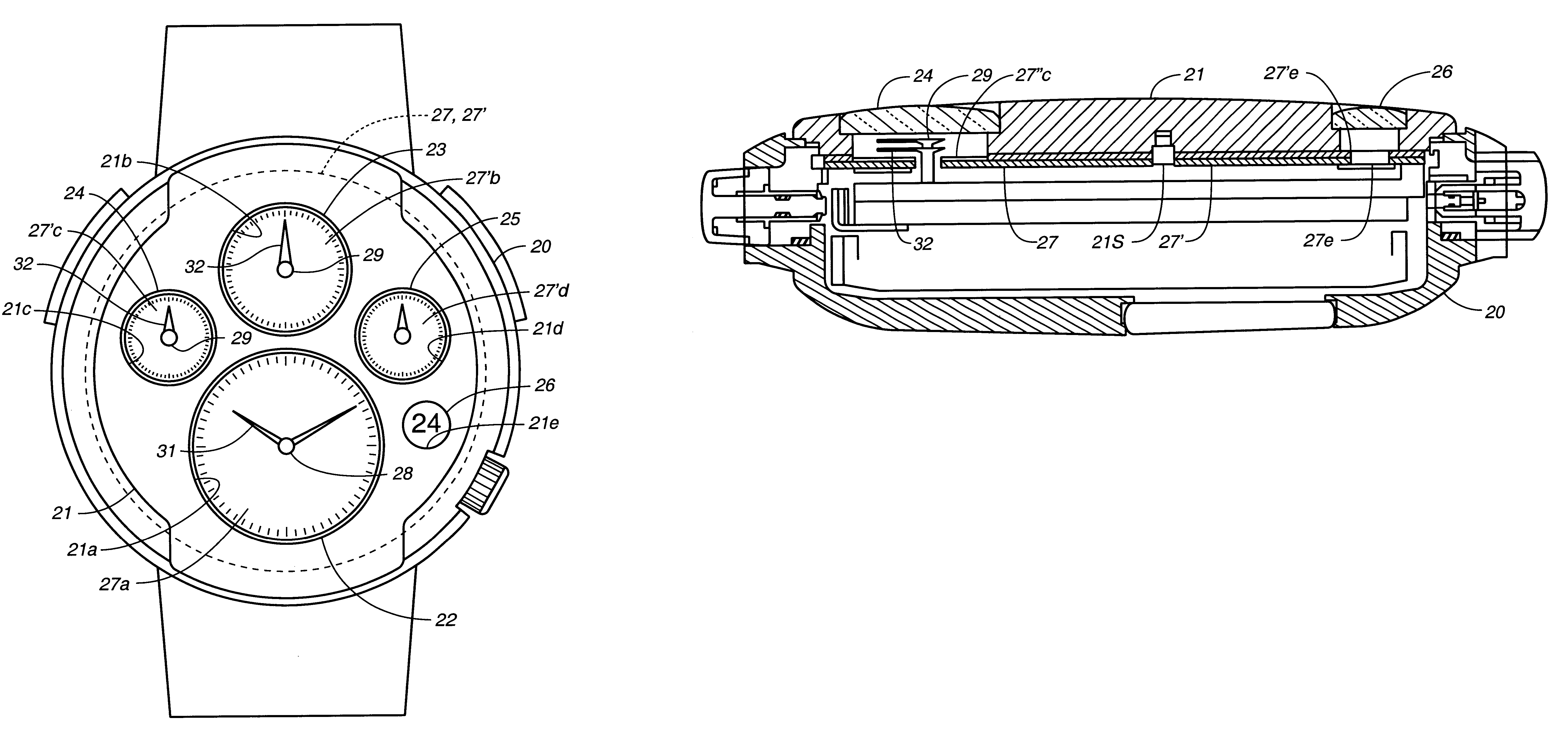
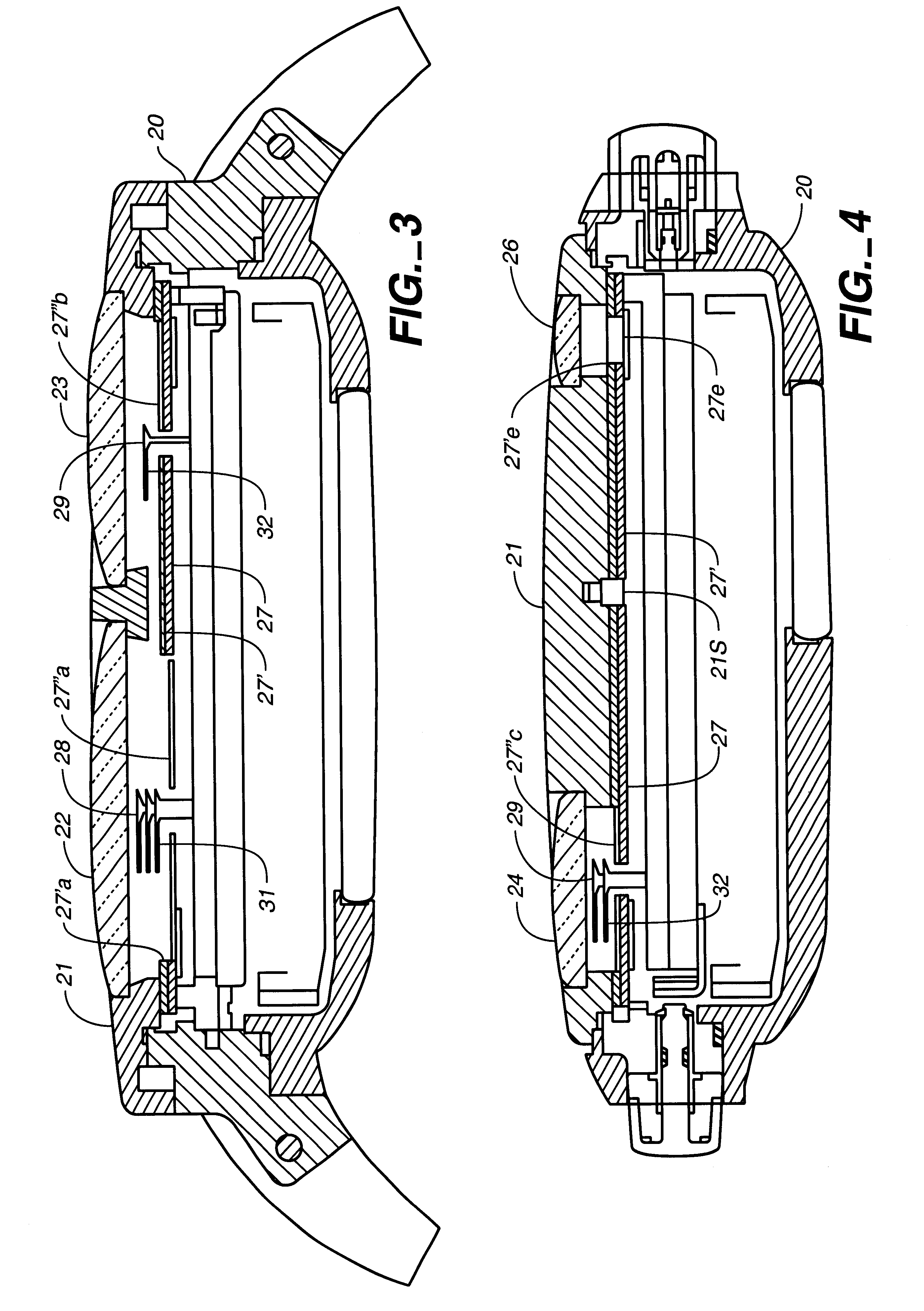
FIG. 1 is a schematic plan view of a display portion illustrating the structure of a watch proper according to a first embodiment of the time piece according to the present invention. This embodiment is a multi-functional wristwatch, and FIG. 1 is a view of this multi-functional wristwatch from a normal direction of visual recognition. A stainless-steel glass framing 21 which is a covering member is attached to the face of the watch case 20. This glass framing 21 is fixed to the watch case 20 by means of caulking or the like. Formed in this glass framing 21 are a main opening 21a and four sub-openings 21b, 21c, 21d, and 21e. Engaged and fixed to these openings are display window members 22, 23, 24, 25, and 26. At least one of these display window members 22, 23, 24, 25, and 26 may be formed of a glass material or transparent resin material serving as a lens to increase visual recognition.

Positioned at the rear side of the glass framing 21 are dials 27 and 27' indic...

second embodiment

[Second Embodiment]

Next, a second embodiment of the time piece according to the present invention will be described with reference to FIG. 5. The present embodiment differs from the above embodiment in that one frame plate 41 is positioned inside the watch case 40 in the state of being pressed by a dial ring 42. Formed to this frame plate 41 are openings 41a, 41b, 41c, and 41d, and positioned within each of these are small dials 44, 45, 46, and 47, each printed with marks or numerals. Needles 51 comprising the time-of-day display system rotate over the dial 44, and needles 52 comprising the sub-indicating systems rotate over the dials 45, 46, and 47. The display window 41e is of the same structure as that of the above first embodiment.

With the present embodiment, one transparent display window member 43 is attached before the time-of-day display system and the sub-indicating systems comprised of the above frame plate 41, dials 44, 45, 46, and 47, needles 51 and 52, etc. Also, with t...

third embodiment

[Third Embodiment]

Next, description will be made regarding the third embodiment of the present invention. This embodiment has an external appearance which is approximately the same as that of the above-described first embodiment, but unlike the first embodiment, has a watch case 50 equivalent to the watch case 20 and glass framing 21 in the first embodiment being integrally formed, as shown in FIG. 6 and FIG. 7, and the structure has a rear lid 61 which screws to the watch case 60 at the opposite side of the time-of-day display potion (i.e., the rear side). The form of the singular watch case 60 is shown in FIG. 10. Incidentally, a display window member 61a is attached to the rear lid 61, making for a rear-lid skeleton structure wherein the watch movement stored within the watch case 60 can be visually confirmed.

Display window members 62, 63, 64, 65, and 66 similar to those in the first embodiment are provided to respective openings at the surface portion of the watch case 60. Also,...


PUM


Abstract

Formed in glass framing (21) attached to a watch case (20) are a main opening (21a) and four sub-openings (21b, 21c, 21d, 21e), with display window members (22, 23, 24, 25, 26) respectively engaged and fixed to each. Positioned at the rear side of the glass framing (21) are dials (27, 27'), and a time-of-day indicating area (27a) which is round to the view when viewed flat is provided to the dial (27). A round opening (27a') corresponding to the time-of-day indicating area (27a) is formed to the dial (27') adhered on the dial 27, and four sub-indicating areas (27b', 27c', 27d') which are round to the view when viewed flat are formed on the surface of the dial (27'). The time-of-day indicating area and sub-indicating areas are arranged so as to be separately viewed by the respective display window members.

Description

TECHNICAL FIELDThe present invention relates to a time piece, and particularly relates to a time piece which has a sub-display system other than a main time display system, such as with a multi-functional watch or the like.BACKGROUND ARTConventionally, common analog wristwatches are configured with a dial 11 provided within a watch case 10, and a display window member 12 formed of a single piece of glass or the like is on the front side of the dial 11, as shown in FIG. 14 and FIG. 15. A through hole is formed in the center of the dial 11, and a main needle driving portion 13 protrudes through this through hole from the movement stored within the watch case 10. Attached to this main needle driving portion 13 are an hour hand 14 and minute hand 15. Also, a plurality of through holes are further formed around the through hole in the dial 11, from which through holes protrude a plurality of sub-needle driving portions 16, with needles 17 attached to each. Further, the dial 11 is designe...

Claims


Application Information

Patent Timeline
IPC IPC(8): G04B39/00G04B19/06G04B37/00G04B37/11
CPCG04B19/06G04B39/008G04B37/11G04B37/0008G04B19/00
Inventor MAKIBA, HIDENORI
Owner SEIKO EPSON CORP
Why Eureka
Try Eureka