Metal roof/wall apparatus including sliding clips

Active Publication Date: 2021-11-23
NELSON JR G PAUL
View PDF58 Cites 2 Cited by
  • Summary
  • Abstract
  • Description
  • Claims
  • Application Information

AI Technical Summary

Benefits of technology

[0013]The wrap-around clip of FIGS. 1-45 allows movement in the roof grid system in a 360-degree radius while achieving superior attachment strength to standard roof clips. Current clips on the market mount on top of the flange of structural metal supports by the use of screws mounting the base of the clip to the top surface of the flange. The new clip design of the present invention can be installed on any style or size of structural member including Z-purlins, C-purlins, wood or steel w

Problems solved by technology

This type of attachment also does not allow for thermal movement of the panels, thus forcing the screws to cut or groove the surrounding metal against the screw shank.
If this slotting of the panel becomes severe enough to exceed the circumference of the screw sealing washer, water will leak into the building.
Due to thermal movement, R-panel lengths are limited to 40 feet.
Screws attached through the R-panel and into the structural member can achieve a maximum of two hundred twenty (220) psi of resistance to wind uplift, but the panel itself cannot norm

Method used


Image

  • Metal roof/wall apparatus including sliding clips
  • Metal roof/wall apparatus including sliding clips
  • Metal roof/wall apparatus including sliding clips

Examples


Embodiment Construction

[0063]The function of each part is preferably as follows:
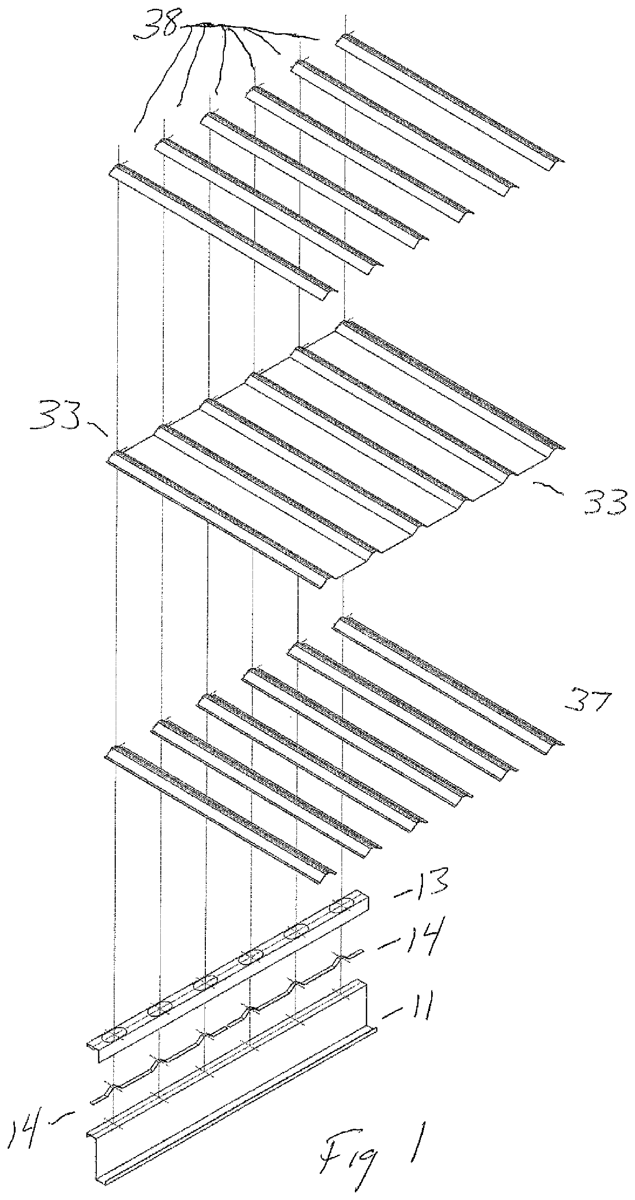
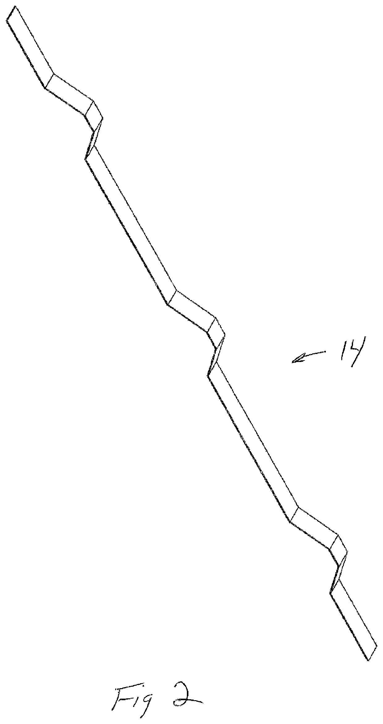
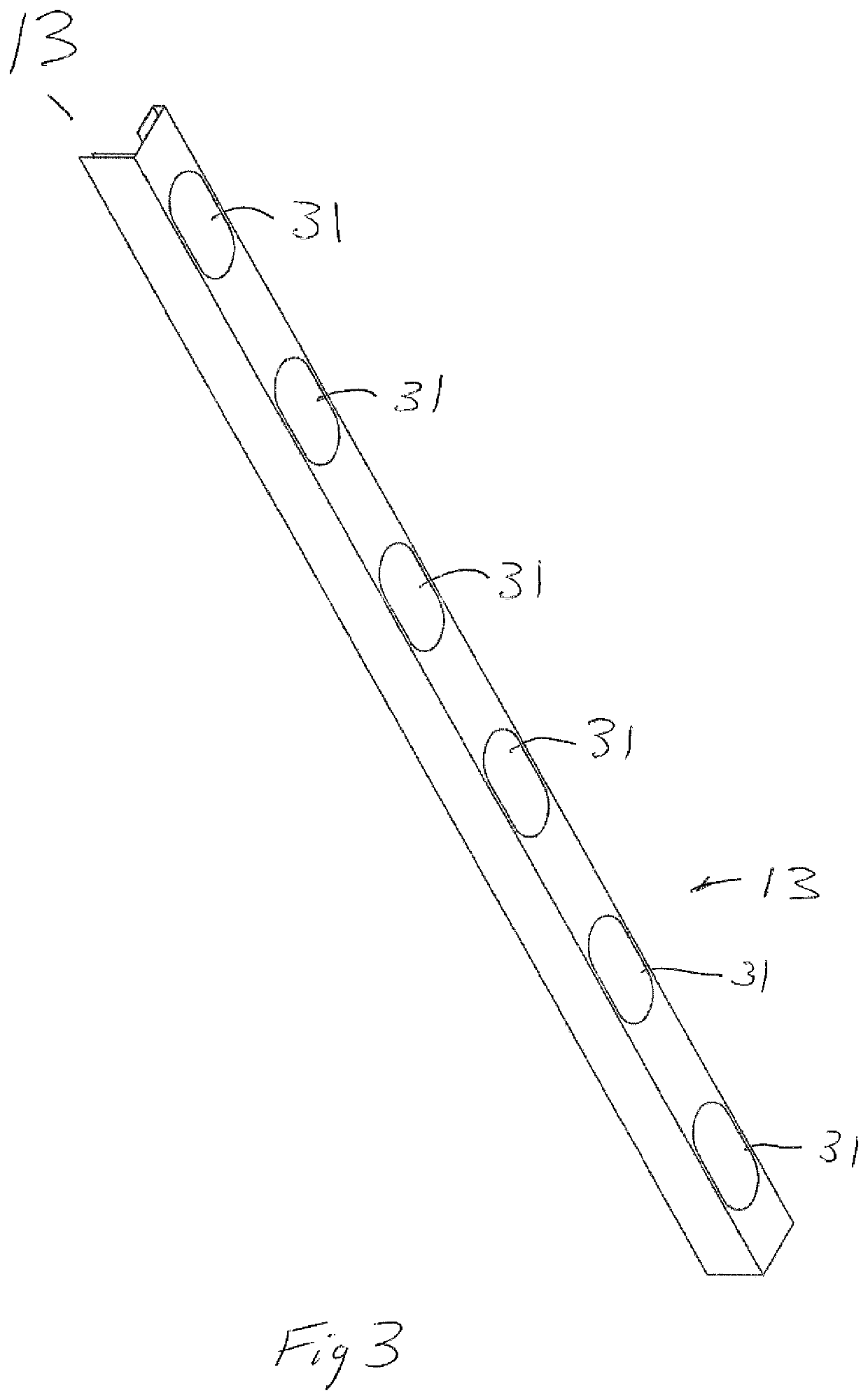
The Anchor Plate

[0064]The anchor plate houses the sliding anchor (FIGS. 1,7,12,21). The sliding anchor is the mechanism that attaches a roof or wall panel to the structural member through the anchor plate. When anchor plates are installed on a member, they are preferably installed abutting each other (FIG. 9). This eliminates the repeated having to pop chalk lines to make sure each anchor point is properly aligned with other anchor points up and down slope of the roof system.

[0065]The anchor plate can be made of one piece of metal shaped to wrap around the top flange of the structural member (FIGS. 8,10,11,13,16,20,22,28,29). However, the anchor plate can also be made of several pieces of metal plate with each plate being made of the same thickness and type of metal or different thicknesses and types of metal. The anchor plate can be any length or width to allow an increase in number of sliding anchor points or an increase in ...


PUM


Abstract

A metal roof construction provides a roof frame that includes multiple rafters. A plurality of clips or anchor plates are fastened to each rafter. Each anchor plate or clip has an anchor plate space surrounded by one or more plate members. The anchor plate has a plurality of spaced apart openings. A sliding anchor occupies the anchor plate space. Each sliding anchor has multiple spaced apart pedestals that extend from the anchor plate space upwardly through an opening. Multiple roof decking sections are mounted on the rafters. Each decking section extends under a part of the anchor plate. The anchor plate has one or more flaps that extend downwardly from the decking sections and next to a rafter. Fasteners attach each flap to a rafter.

Description

CROSS-REFERENCE TO RELATED APPLICATIONS[0001]This application claims priority of my U.S. Provisional Patent Application Ser. No. 62 / 642,133, filed 13 Mar. 2018, and my U.S. Provisional Patent Application Ser. No. 62 / 703,980, filed 27 Jul. 2018, both of which are hereby incorporated herein by reference.STATEMENT REGARDING FEDERALLY SPONSORED RESEARCH OR DEVELOPMENT[0002]Not applicableREFERENCE TO A “MICROFICHE APPENDIX”[0003]Not applicableBACKGROUND OF THE INVENTION1. Field of the Invention[0004]The present invention relates to a roofing and / or wall system employing wrap-around roof / wall clips, support grid, roofing / wall panels and flashing clips. The present invention provides a specially configured clip apparatus that will allow movement in the roof panels in a 360-degree radius while achieving superior attachment strength when compared to standard roof clips. Mechanical attachments are based on utilizing the stronger properties of shearing verses pullout. The present invention all...

Claims


Application Information

Patent Timeline
IPC IPC(8): E04D1/30E04D3/362E04D3/30E04D3/366E04D3/361
CPCE04D3/362E04D1/30E04D3/30E04D3/366E04D2003/3615E04D3/364
Inventor NELSON, JR., G. PAUL
Owner NELSON JR G PAUL
Why Eureka
Try Eureka