Method of controlling fluid flow transfer in shoes

a technology of fluid flow and shoe structure, applied in the field of fluid transfer, can solve the problems of not being recognized or provided a solution, and prior art does not provide shoe structure capable of quick and simple techniqu

Inactive Publication Date: 2001-09-04
CASTON GAYFORD
View PDF15 Cites 46 Cited by
  • Summary
  • Abstract
  • Description
  • Claims
  • Application Information

AI Technical Summary

Problems solved by technology

The prior art however has not recognized or provided a solution to successfully apply the principle of fluid transfer for ankle support in shoes generally and particularly in running shoes In addition, prior art fluid transfer devices are constructed based upon predetermined conditions applicable regardless of variations in shoe size or weight of the user.
Additionally, the prior art does not provide shoe structure capable of a quick and simple technique to vary and adjust the pressure within a fluid cavity corresponding to the weight or shoe size of the wearer.

Method used


Image

  • Method of controlling fluid flow transfer in shoes
  • Method of controlling fluid flow transfer in shoes
  • Method of controlling fluid flow transfer in shoes

Examples


Embodiment Construction

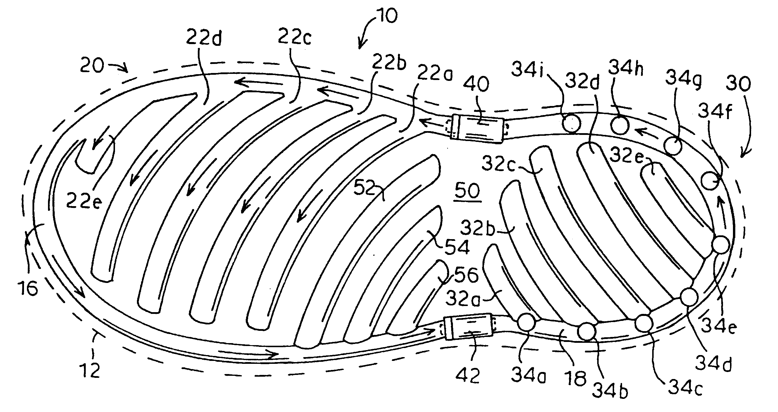
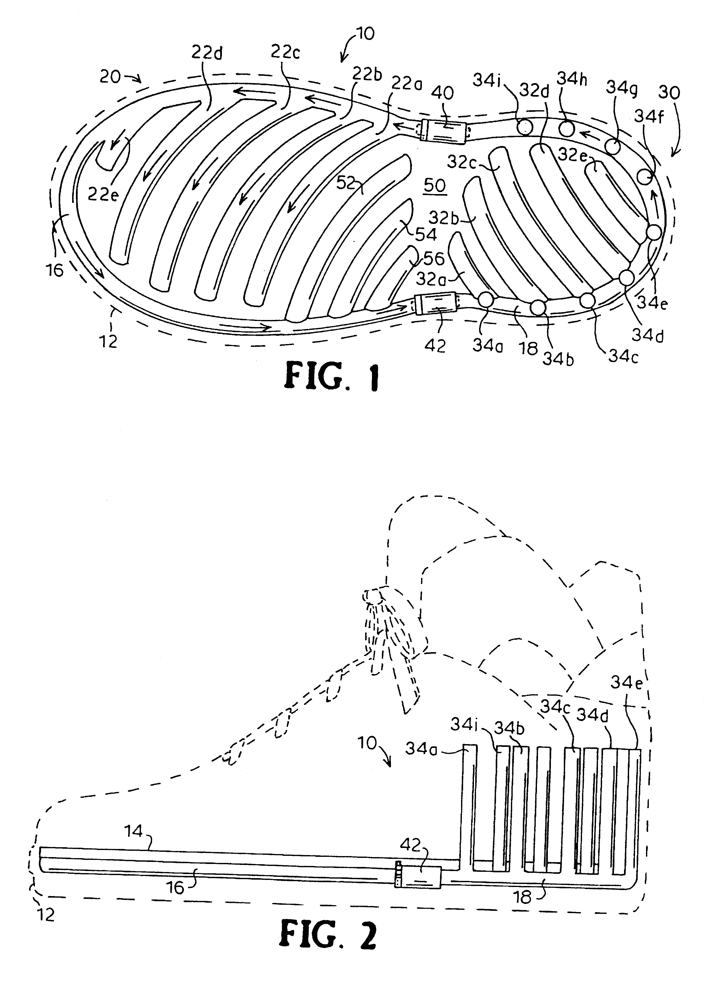
Referring to the drawings, and initially to FIG. 1, a preferred embodiment of the fluid transfer shoe 10 of the invention is illustrated generally. Fluid transfer shoe 10 has an outer sole 12 and a front chamber 20 that receives and supports the forward part of the foot of a user above outer sole 12. Front chamber 20 has a fluid filled outside toe periphery tube 16 and a plurality of ball of foot cross tubes or front bubble inlets 22a, 22b, 22c, 22d, and 22e. Each of the ball of foot cross tubes or front bubble inlets 22a-22e connects with front chamber 20 providing a plurality of fluid flow paths within fluid transfer shoe 10, from outside toe periphery tube 16 for providing a cushion for the phalanges or toes including the ball portion of the foot of the user.

Still referring to FIG. 1, fluid transfer shoe 10 has a rear chamber 30 that receives and supports the rear part of the foot of the user above outer sole 12. Rear chamber 30 has a fluid filled outside heel periphery tube 18 a...


PUM


Abstract

A method and apparatus for sing the flow of fluid through tubes in the sole of shoes. The apparatus includes a pair of fluid filled tubes along the periphery of the sole of the shoe. One tube is connected to cross tubes that provide flow paths and cushions the for the ball and instep portions of the foot. The other tube is connected to cross tubes that provide flow paths and cushions heel portion of the foot. Adjustable pressure valves interposed between the fluid filled tubes permit a method of controlling the flow of fluid through the valves in one direction only. The pressure resistance of the valves are pre-set for a certain internal pressure level required for triggering the transfer of fluid from one tube to the other. The method include steps of controlling pressure resistance by adjusting valve pressure adjustment rings either in a clockwise direction about a rod for increasing internal pressure resistance, or in a counter-clockwise direction for decreasing internal resistance.

Description

1. Field of the InventionThis invention relates to transfer of fluid to achieve shock absorption in footwear, and in particular, relates to fluid transfer for shock absorption and ankle support adjustable to compensate for differences in shoe size or body-weight of a user.2. Background of the Prior ArtThe basic concept of shock absorption in shoes with transfer of fluid between the heel to the ball portion of a user's foot has been known as illustrated in previously issued U.S. Patents for example, U.S. Pat. No. 4,312,140 by Reber discloses a device to facilitate pedestrians comprising a heel cavity that is connected via a feedback tube to a cavity located in the front part of the sole of a shoe. The '140 patent teaches that when the heel impacts the ground the compression results in a closing of the feedback tube which is connected to a first reservoir which includes a first one-way valve thus causing a decrease in the inner volume. As a result of this decrease of volume, pressure ...

Claims


Application Information

Patent Timeline
Patent Type & Authority Patents(United States)
IPC IPC(8): A43B13/18A43B13/20A43B21/00A43B21/26A43B23/07A43B23/00
CPCA43B13/203A43B23/07A43B21/265A43B13/206A43B7/20A43B23/029
Inventor CASTON, GAYFORD
Owner CASTON GAYFORD
Why Eureka
Try Eureka