Fast low-power logic gates and method for evaluating logic signals

a logic gate, low-power technology, applied in logic circuits, logic circuits, logic circuits characterised by logic functions, etc., can solve the problems of slow logic gates that use them, more current drawn, evaluation speed and power consumption

Inactive Publication Date: 2001-09-18
IBM CORP
View PDF5 Cites 22 Cited by
  • Summary
  • Abstract
  • Description
  • Claims
  • Application Information

AI Technical Summary

Problems solved by technology

This topology has a disadvantage in that the logic gates that use it are slow.
A limitation of the wide OR and deep AND topologies is that a pullup (in the case of the wide OR) or pulldown (in the case of deep AND) circuit must be present for the node to be set to a proper voltage level when all of the input transistors are not conducting.
Disadvantageously, the faster this change is made (due to a larger-sized pullup or pulldown), the more current is drawn through the logic gate when at least one of the transistors is held in the conducting state.
For these topologies, evaluation speed and power consumption are a design tradeoff.

Method used


Image

  • Fast low-power logic gates and method for evaluating logic signals
  • Fast low-power logic gates and method for evaluating logic signals
  • Fast low-power logic gates and method for evaluating logic signals

Examples


second embodiment

Referring now to FIG. 5, the present invention is depicted. This embodiment is a deep AND static logic gate. For this topology, the roles of the PMOS and NMOS transistors are reversed, as is the operation of Control 22.

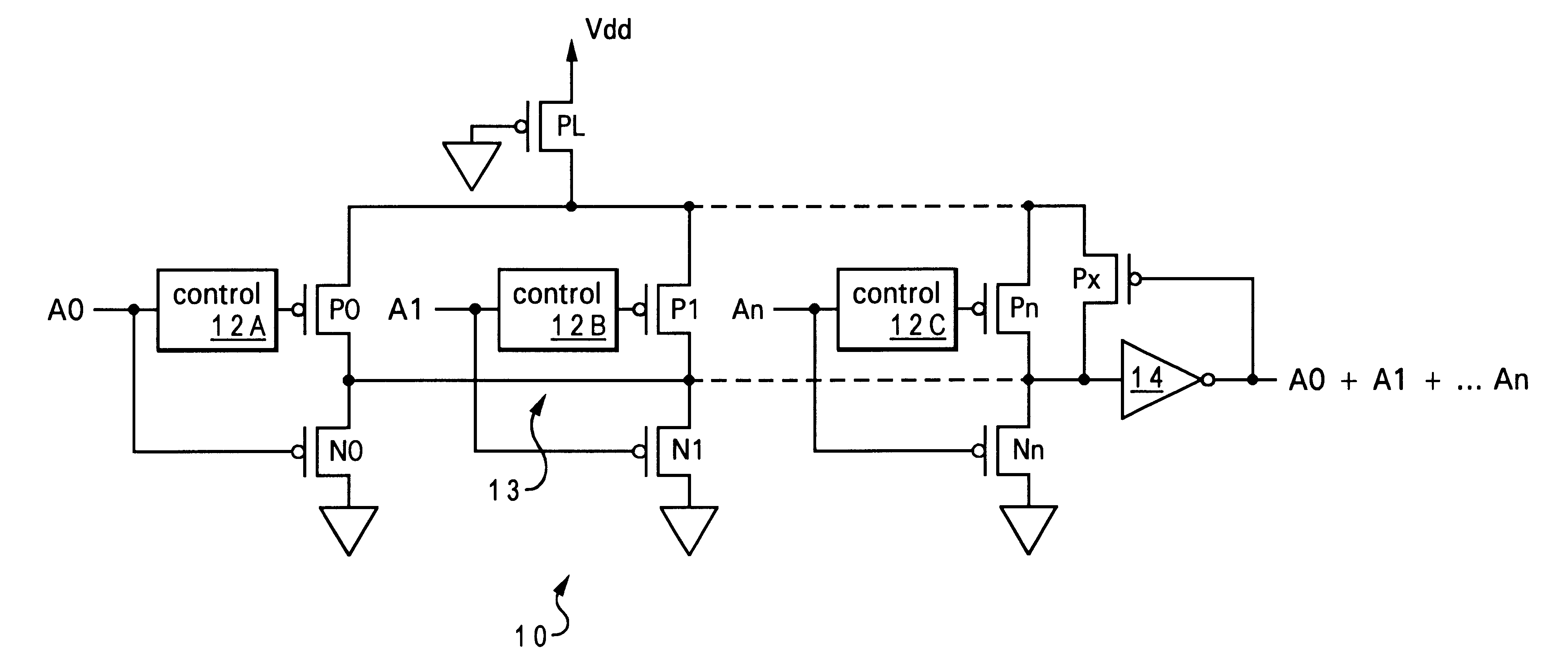
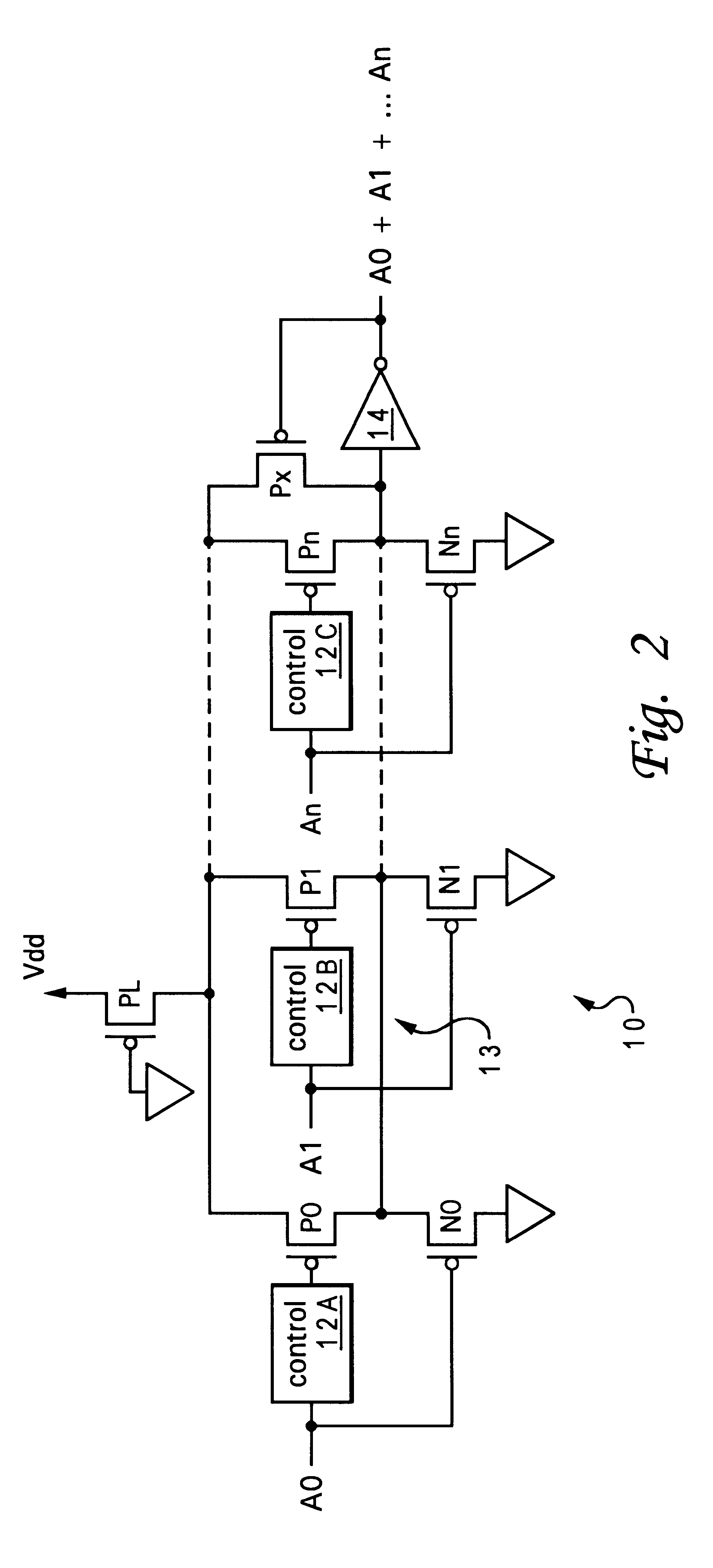
Deep AND gate 20 takes inputs A0 through Am and generates an output A0.multidot.A1.multidot. . . . Am, where ".multidot." indicates a logical AND operator, and both the drawing and the equation are drawn to illustrate that more input ladders can be connected to summing node 23, in order to add more "AND" terms to the equation. PMOS ladder transistors P10 through Pm are connected to summing node 23. If any of inputs A0 through Am are in a logic low state, the PMOS transistors connected to those inputs will turn on, pulling summing node 23 to Vdd, the positive rail. Pulldown NMOS transistors N10 through Nm are enabled by control circuits 22. NMOS transistor NL acts limits the total current that can be drawn from summing node 23 to ground, so that if more than one pulldo...

third embodiment

Referring now to FIG. 8 a combination wide OR stacked AND logic gate 30 is depicted in accordance with the invention. This gate is similar in operation to the wide OR 10 of FIG. 2. Input ladders in this gate 30 comprise more than one NMOS transistor, in order to perform and AND function. The ladders are connected to summing node 33 in parallel to provide the OR function, resulting in an evaluation of (A0.multidot.A1)+ . . . +(Aj.multidot. . . . Ai) Since all of the NMOS transistors in a ladder must be conducting for the ladder to pull down summing node 33, the contribution of each ladder is a NAND function. Summing node 33 produces the logical AND of all the NAND contributions, since it will be pulled low if any of the ladders conduct, and inverter 34 inverts this AND result to produce NAND of NAND contributions, which by De Morgan's theorem results in OR of AND contributions.

For circuits having ladders with more than one transistor, a control 12 is provided for every transistor in ...


PUM


Abstract

Fast low-power logic gates and method for evaluating logic signals reduce the effect of the power / speed tradeoff for parallel connected logic. A control circuit momentarily enables a high-current pullup or pulldown device after a connected input ladder switches from a conducting state to a non-conducting state. This allows a high current pullup or pulldown to be used for fast evaluation without increasing overall current drain, since the pullup action is momentary.

Description

1. Technical FieldThe present invention generally relates to logic gates, and more particularly to static logic gates with low power consumption and short evaluation times.2. Description of the Related ArtLogic circuits, particularly those used to simultaneously evaluate an equation with a large number of inputs have been implemented in a variety of architectures. Among static logic gates, which require no preset signals and maintain their output state as long as the input signals remain in the same state, two standard architectures are well known in Metal-Oxide-Semiconductor (MOS) implementations.In order to evaluate an OR equation, as shown in FIG. 1A, ladders of PMOS transistors (with each gate coupled to a logic input and the bottom of the ladder connected to ground) are stacked in series so that if any logic input is high, the ladder will not conduct and therefore produce a logic high output at the top of the ladder. In order to evaluate an AND equation, a similar ladder can be...

Claims


Application Information

Patent Timeline
Patent Type & Authority Patents(United States)
IPC IPC(8): H03K19/00H03K19/0948
CPCH03K19/0948H03K19/0013
Inventor DHONG, SAND HOONGO, HUNG CAIPARK, JAEHONGTAKAHASHI, OSAMU
Owner IBM CORP
Why Eureka
Try Eureka