Cordless dryer safety interlock system

a safety interlocking and hair dryer technology, applied in the direction of air-break switch, contact mechanism, transportation and packaging, etc., can solve the problem that the safety of the portable hair dryer disclosed by these patents is not included

Inactive Publication Date: 2001-11-06
CONAIR CORP
View PDF17 Cites 39 Cited by
  • Summary
  • Abstract
  • Description
  • Claims
  • Application Information

AI Technical Summary

Problems solved by technology

The portable hair dryers disclosed by these patents do not include safety features that assure against operation of the fan when the dryer is seated in the base or against arcing upon insertion or removal of the dryer from the base.

Method used


Image

  • Cordless dryer safety interlock system
  • Cordless dryer safety interlock system
  • Cordless dryer safety interlock system

Examples


Embodiment Construction

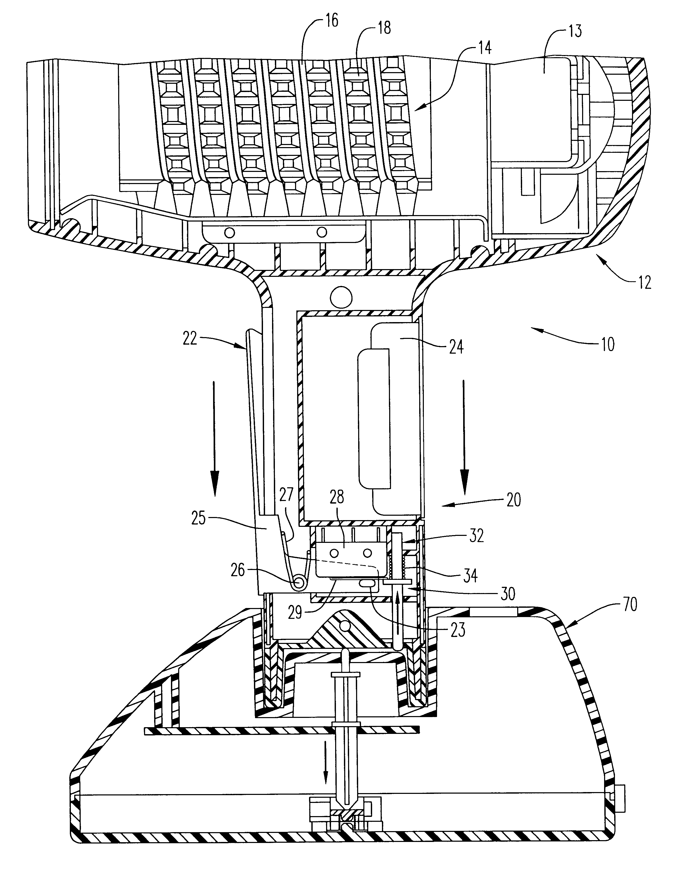
Referring to FIG. 1, a portable hair dryer 10 includes an air flow generating portion 12 (shown in part), a handle 20 and a base 70. A fan 13 and a heater 14 are located in air flow generating portion 12. Heater 14 includes an electrical resistor 16 and a ceramic heating body 18. When handle 20 is inserted into base 70, electrical resistor 16 is supplied with electrical power and heats ceramic heating body 18. Air flow generating portion 12, heater 14 and fan 13 are shown in part.

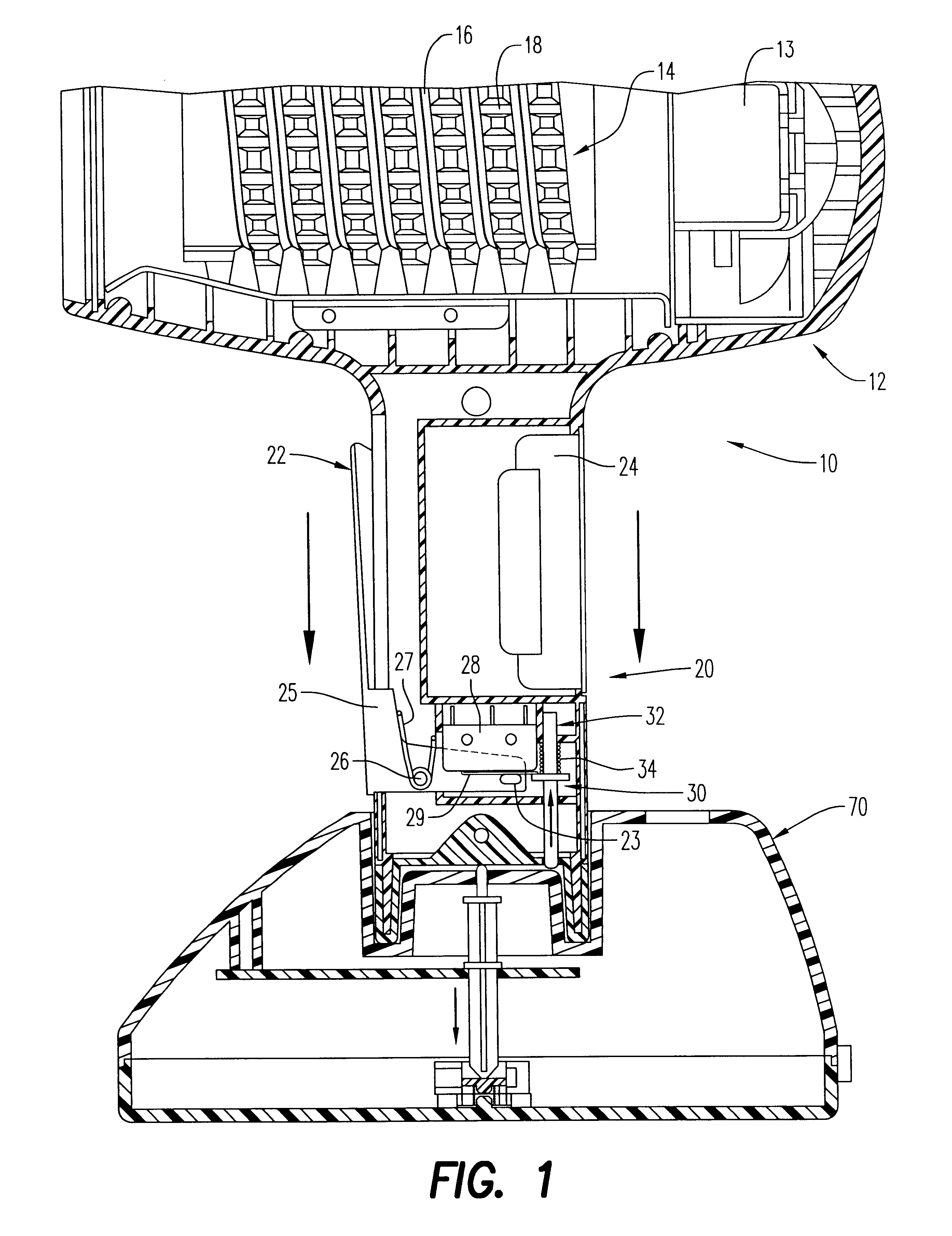
An operator trigger 22 is located along side of handle 20. A battery 24, a switch 28 with a switch lever 29 and an interlock 30 are located in handle 20 Switch 28 includes a spring (not shown) that biases switch lever 29 to an open position in which its switch contacts (not shown) are opened.

Operator trigger 22 has an L-shaped bottom plate 25 that is rotatable about a pivot 26. Trigger 22 is normally biased away from handle 20 by a sorina 27 to an open position that is shown in FIG. 1. Bottom plate 25 inclu...


PUM


Abstract

A hair dryer having a heater, a fan positioned to form an air flow that is heated by the heater, a battery and a switch connected in circuit with the fan and the battery. An interlock prevents the switch from closing during the time the hair dryer is inserted in a base for charging the battery and heating the heater via an electrical power source. An arc prevention assembly prevents arcing among contacts on the hair dryer and the base during insertion and removal of the dryer to and from the base.

Description

This invention relates to a hair dressing appliance and, in particular, to a portable hair dryer that is usable without an electrical cord.DESCRIPTION OF THE ARTU.S. Pat. No. 4,757,183 discloses a cordless portable hair dryer that has heater and a fan that forms an air stream that is heated by the heater. The portable hair dryer includes a battery for operating the fan and an electrical resistor that heats the heater. When not in use, the hair dryer is seated in a base that supplies electrical power to recharge the battery and to cause the resistor to heat the heater. International Patent Publication No. WO 99 / 01049 discloses a similar cordless portable hair dryer in which, when seated in the base, the battery and resistor are separately powered. The portable hair dryers disclosed by these patents do not include safety features that assure against operation of the fan when the dryer is seated in the base or against arcing upon insertion or removal of the dryer from the base.An objec...

Claims


Application Information

Patent Timeline
Patent Type & Authority Patents(United States)
IPC IPC(8): A45D20/10A45D20/00
CPCA45D20/10A45D2020/128
Inventor TAYLOR, HAROLD R.
Owner CONAIR CORP
Why Eureka
Try Eureka