
Continuous multi-satellite tracking

a multi-satellite, satellite technology, applied in the direction of antennas, simultaneous aerial operations, electrical equipment, etc., can solve the problems of difficulties to which will be made reference hereinafter

Inactive Publication Date: 2001-12-25
ELECTRONIQUE MARCEL DASSAULT SA
View PDF7 Cites 33 Cited by
  • Summary
  • Abstract
  • Description
  • Claims
  • Application Information

AI Technical Summary

Problems solved by technology

However, difficulties to which reference will be made hereinafter are encountered in the case of the constraining requirements of cost and / or overall dimensions (weight and volume), as is the case in general public electronics.

Method used


Image

  • Continuous multi-satellite tracking
  • Continuous multi-satellite tracking
  • Continuous multi-satellite tracking

Examples


Embodiment Construction

The attached drawings are to scale and of a specific nature. Thus, not only can they be used to facilitate understanding of the following detailed description, but can also contribute to the definition of the invention, when appropriate.

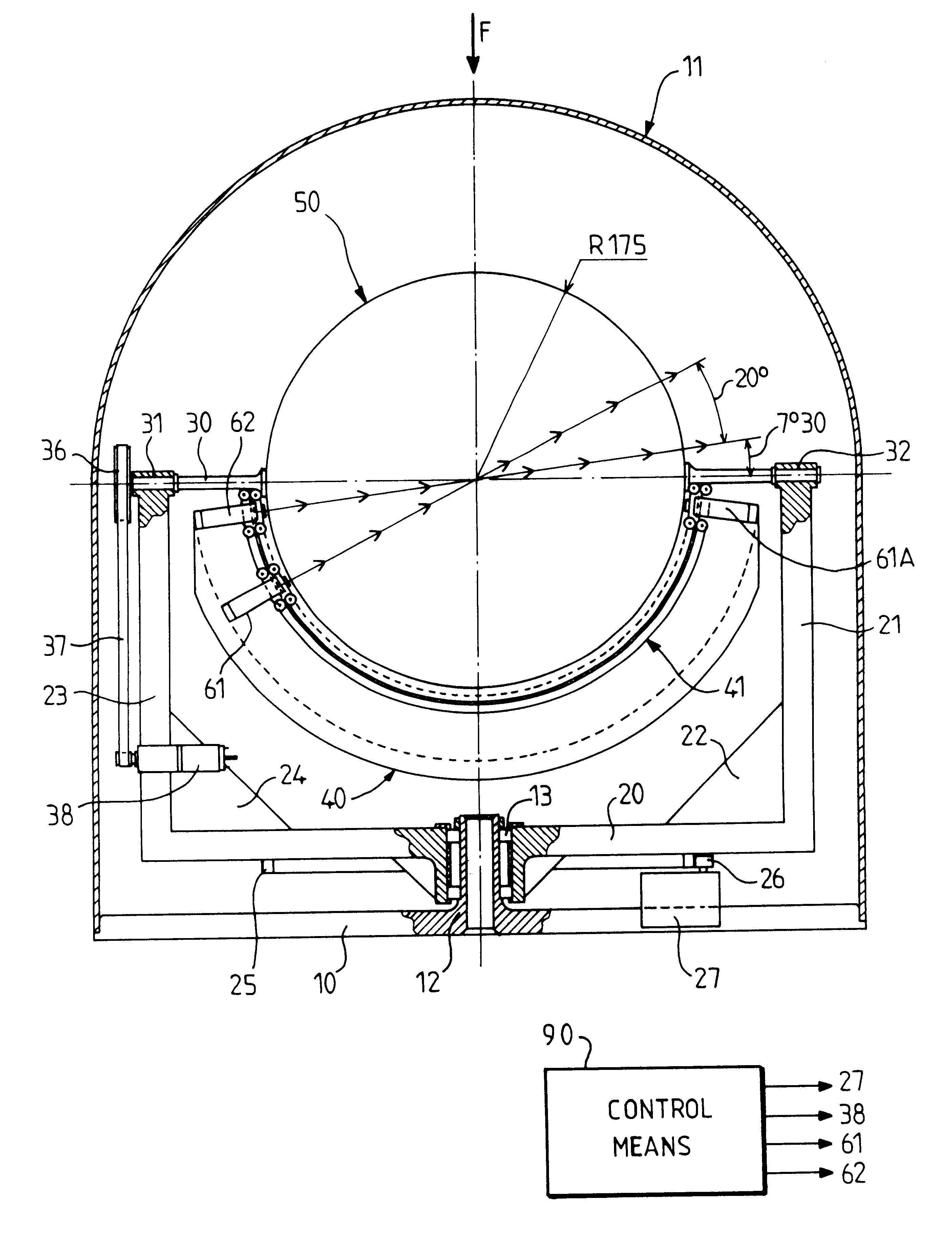
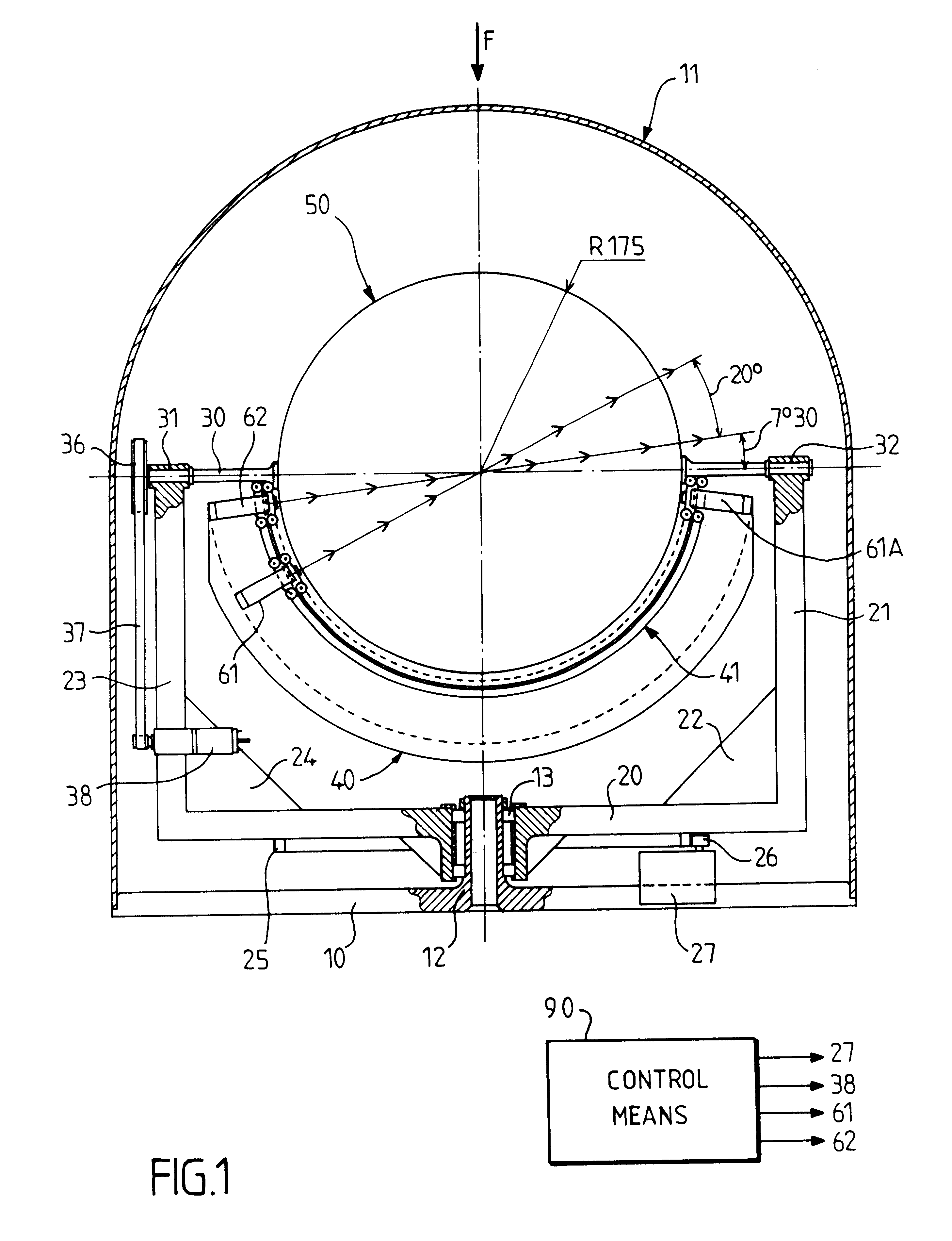
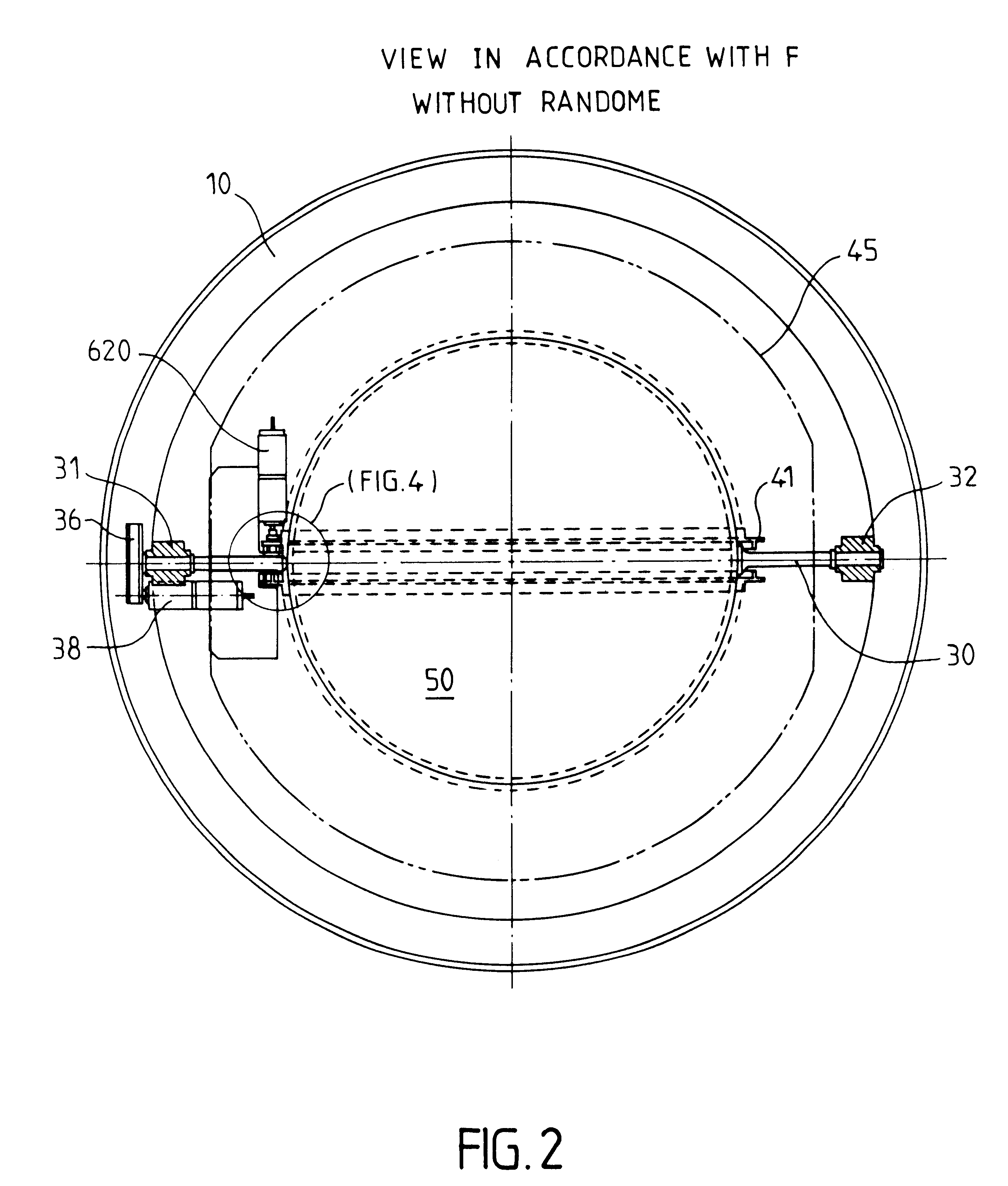
In FIG. 1, the device has a support 10, which supports a radome 11, whereof the base is generally cylindrical and the upper part is a spherical halfdome. In the centre, the support 10 carries a hollow shaft 12, about which is mounted a ball bearing 13, which supports a generally U-shaped frame 20, whereof the ends of the branches support bearings 31 and 32. Reinforcing ribs 22 and 24 are provided between the branches of the U. Similar, not referenced ribs are provided about the axis in the frame 20, whilst the lower part thereof is provided with a ring gear 25, which cooperates with the roller 26 of a drive motor 27 mounted on the support 10.

The bearings 31 and 32 support two half-shafts 30, rendered integral with a sphere 50, along one of its large ...


PUM


Abstract

The pointing of at least two sensors (61, 62) is ensured through a Luneberg lens (50). A first frame (20) pivoting on a support (10), supports in pivoting manner a second frame (30), which can in turn support the lens (50). The second frame (30, 40) supports at least one rail (41) for guiding the sensors in the vicinity of the focal surface of the lens. Control means (90) act on the mount as a function of data concerning the position of satellites to be sighted. They are arranged so as to temporarily stop the sighting of one of the satellites, bring the mount into an opposite position on the focal surface, whilst continually sighting the other satellite, and resume the sighting of both satellites, the two sensors then being in an inverted position on the rail.

Description

1. Field of the InventionThe invention relates to the tracking of satellites, particularly from earth.2. Discussion of the Prior ArtThe importance of satellite communications is already known and will increase in the future. Apart from the presently used geostationary satellites, it is also intended to launch constellations of nonsynchronous satellites, for broadband, high speed telecommunications applications.It is naturally also necessary to provide ground stations able to track several of these satellites at the same time. The basic procedures to be used are known and are already used in professional electronics. However, difficulties to which reference will be made hereinafter are encountered in the case of the constraining requirements of cost and / or overall dimensions (weight and volume), as is the case in general public electronics.The present invention aims at improving this situation.It is based on an electromagnetic, multi-satellite reception device comprising at least two...

Claims


Application Information

Patent Timeline
IPC IPC(8): H01Q19/06H01Q3/00H01Q5/00H01Q19/00H01Q25/00H01Q3/14H01Q5/45
CPCH01Q3/14H01Q5/45H01Q25/008H01Q19/062
Inventor PONCEL, YVESFREYSSINIER, PHILIPPE
Owner ELECTRONIQUE MARCEL DASSAULT SA
Learn More